Moving object detection system

A technology for moving objects and detection systems, which can be used in radio wave measurement systems, collision avoidance systems, traffic control systems, etc., and can solve problems such as misidentification of multiple reflection points.

Active Publication Date: 2012-11-28
DENSO CORP
View PDF5 Cites 27 Cited by
  • Summary
  • Abstract
  • Description
  • Claims
  • Application Information

AI Technical Summary

Problems solved by technology

This can cause the moving object detection system to misidentify the multiple ref

Method used


Image

  • Moving object detection system
  • Moving object detection system
  • Moving object detection system

Examples


no. 1 example

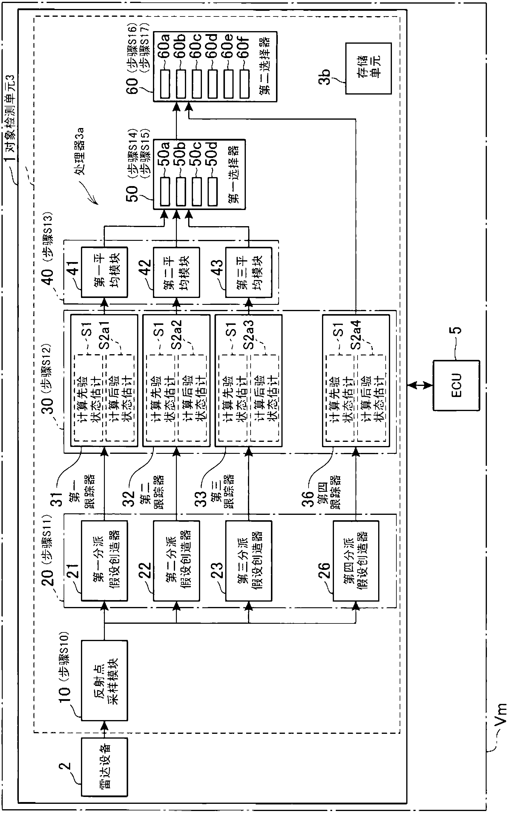
[0053] figure 1 An example of the overall structure of the moving object detection system 1 according to the first embodiment of the present disclosure is shown in . The moving object detection system 1 and the ECU 5 are installed in a motor vehicle (vehicle) Vm. The moving object detection system 1 is communicably connected to the ECU 5 and includes a radar device 2 and an object detection unit 3 . The radar device 2 is communicably connected to the detection unit 3 .

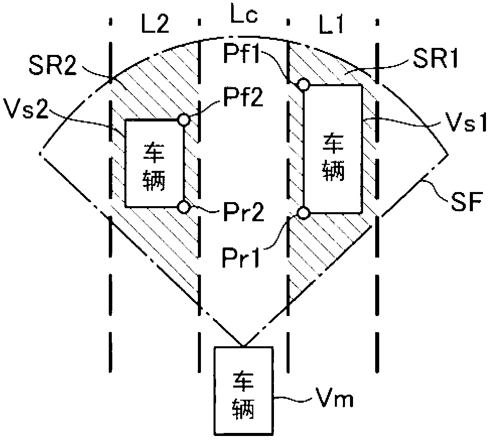
[0054] The radar device 2 is placed on, for example, the front end (head) of the vehicle Vm. The radar device 2 is designed to transmit millimeter radio waves as search waves via a transmitting antenna in the forward direction of the vehicle Vm corresponding to the vehicle traveling direction. The radar device 2 is designed to search for a predetermined scan field SF by scanning the scan field SF using radio waves. The scan field SF extends from the radar device 2 of the vehicle Vm in the form of, for exam...

no. 2 example

[0219] will be referred to below Figure 5A A moving object detection system 1A according to a second embodiment of the present disclosure is described.

[0220] The structure and / or function of the moving object detection system 1A according to the second embodiment differs from the moving object detection system 1 in the following points. Therefore, different points will be mainly described below.

[0221] The mobile object detection system 1A includes a radar device 2 and an object detection unit 3A communicably connected thereto.

[0222]The object detection unit 3A comprises a reflection point sampling module 10 , an assignment hypothesis creator 25 , a fourth assignment hypothesis creator 26 , a tracker 35 , a fourth tracker 36 , an averaging module 45 and a selector 61 .

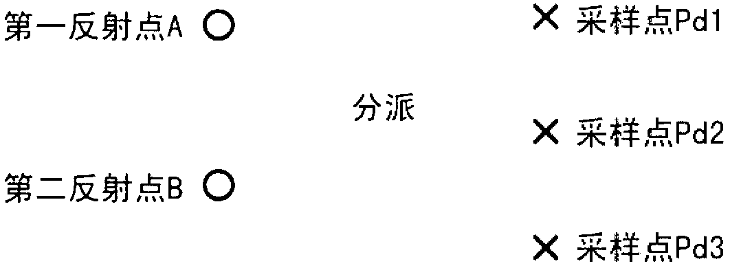
[0223] The assignment hypothesis creator 25 is operatively connected to the reflection point sampling module 10 and is designed to create an assignment hypothesis under an average model of the dynam...

no. 3 example

[0243] will be referred to below Figure 5B A moving object detection system 1B according to a third embodiment of the present disclosure is described.

[0244] The structure and / or function of the moving object detection system 1B according to the third embodiment differs from the moving object detection system 1 in the following points. Therefore, different points will be mainly described below.

[0245] The mobile object detection system 1B includes a radar device 2 and an object detection unit 3B communicably connected thereto.

[0246] The object detection unit 3B includes a reflection point sampling module 10 , an assignment hypothesis creator 25 , a fourth assignment hypothesis creator 26 , a fourth tracker 36 and a selector 62 .

[0247] The selector 62 is operatively connected to the fourth tracker 36 .

[0248] The selector 62 is designed to perform the following routine to determine the fourth model M based on the kth sample 0 The posterior state estimate x k|k...


PUM


Abstract

In a system, a detection module periodically detects position information of a reflection point of a received back wave. A sampling module periodically samples a first reflection point and a second reflection point for the detected reflection points of the each period. The first and second reflection points are expected to be reflection points of first and second reflection parts of a moving object in front of the system. A first determination module determines whether a distance between the first reflection point and the second reflection point changes along with time. In the case of determining that the distance between the first reflection point and the second reflection point does not change along with time, a second determination module determines the reflection points of the first and second reflection parts of the single moving object corresponding to the first and second reflection points.

Description

technical field [0001] The present disclosure generally relates to a moving object detection system that transmits search waves, receives echoes based on the search waves, and detects moving objects based on the received echoes. Background technique [0002] Moving object detection systems are installed in motor vehicles to improve their driving safety. A typical moving object detection system installed in a motor vehicle transmits radar waves in front of the motor vehicle and receives echoes from moving objects in front of the motor vehicle; these echoes are generated based on the radar waves. The moving object detection system detects moving objects based on received echoes. [0003] Such a moving object detection system using echoes based on emitted radar waves can detect a plurality of reflection points in a single moving object; the plurality of reflection points reflect radar waves emitted from the moving object detection system. This may cause the moving object dete...

Claims


Application Information

Patent Timeline
IPC IPC(8): G01S13/02G01S13/93G01S13/931
CPCG01S13/726G01S7/354G01S7/2923G01S13/42G01S13/58G01S2013/9375G01S2013/9321G01S2013/9325G01S2013/9346G01S13/931G01S2013/93185G01S2013/93271G08G1/166G08G1/16G08G1/015G01S13/93
Inventor 水谷玲义铃木幸一郎高野岳
Owner DENSO CORP
Why Eureka
Try Eureka