
Hydraulic mem-inerter device and application thereof
A technology of memorizing container and hydraulic force, applied in the field of hydraulic inertia container device, can solve the problem of not finding mechanical devices, and achieve the effect of continuous adjustment and control, good control or counteracting vibration force, and deepening mutual connection.
- Summary
- Abstract
- Description
- Claims
- Application Information
AI Technical Summary
Problems solved by technology
Method used
Image

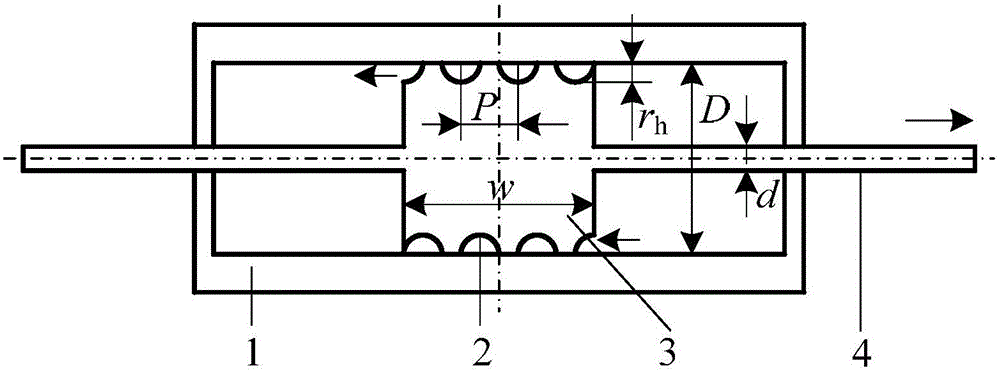
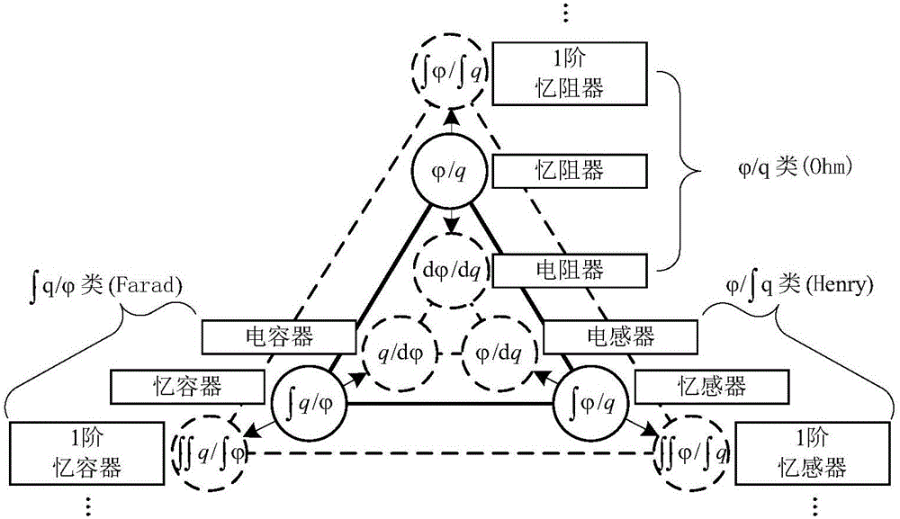
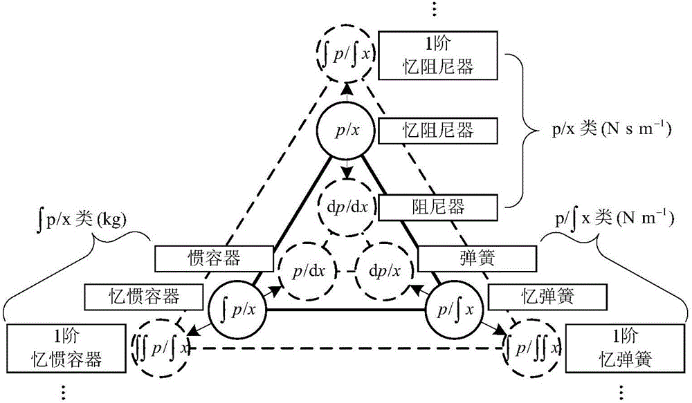
Examples
Embodiment Construction
[0034] The present invention will be further described below in conjunction with drawings and embodiments.
[0035] Figure 4 It is the first embodiment of the hydraulic memory container device, including a first cylinder 1, a first piston 3, and a liquid 7. The first cylinder 1 has two inner circular surfaces with different diameters, which are respectively large inner circular surfaces 5 and small inner circular surface 6, and the entire interior of the first cylinder 1 is filled with liquid 7; the outer surface of the first piston 3 cooperates with the small inner circular surface 6 of the cylinder to divide the first cylinder 1 into There are two left and right cavities, the outer surface of the first piston 3 is provided with a spiral groove 2, and the spiral passage surrounded by the spiral groove 2 and the small inner circular surface 6 connects the left and right cavities of the first cylinder 1. When the first piston 3 moves relative to the first cylinder 1, the firs...
PUM
 Abstract
Description
Claims
Application Information