Click on the blue label to locate the original text in one second.
Reading with bidirectional positioning of images and text.
Examples
Embodiment 1
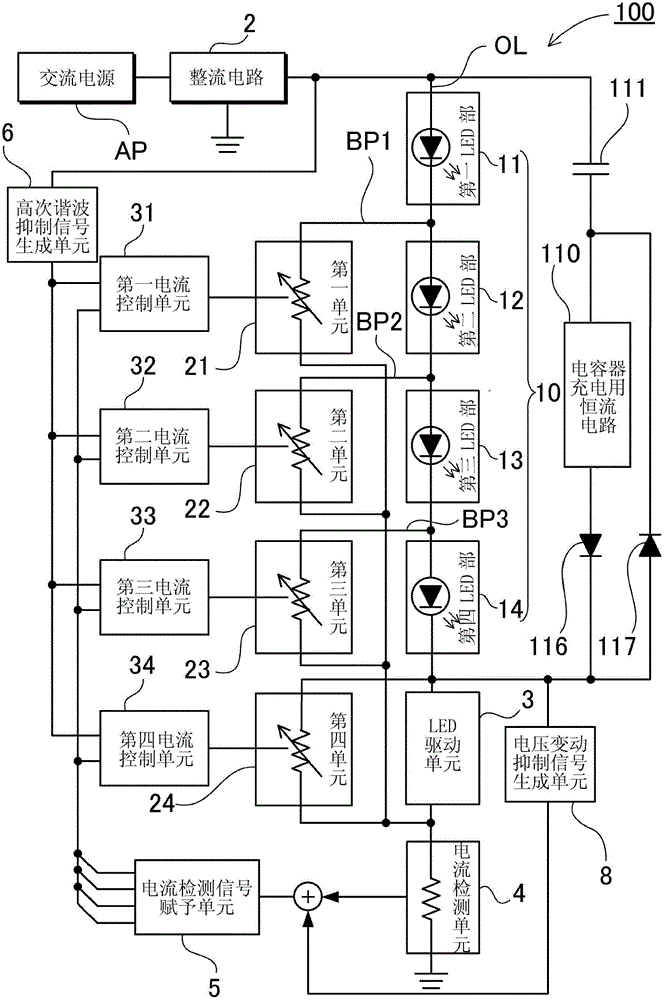
[0074] figure 1 A block diagram of the light emitting diode driving device 100 according to the first embodiment is shown in . This LED drive device 100 includes a rectifier circuit 2 , an LED assembly 10 , a first unit 21 to a fourth unit 24 , a first current control unit 31 to a third current control unit 33 , and a current detection unit 4 . In this light emitting diode driving device 100, a rectifier circuit 2 connected to an AC power supply AP to obtain a rectified voltage (pulsating current voltage) after rectifying the AC voltage, and a rectifier circuit 2 composed of a plurality of LED units are connected in series to the output line OL. LED assembly 10 . Here, four LED units are used, and the first LED unit 11 , the second LED unit 12 , the third LED unit 13 , and the fourth LED unit 14 are connected in series to form the LED assembly 10 . Furthermore, the LED assembly 10, the LED drive unit 3, and the current detection unit 4 are connected in series to the output ...
PUM
Abstract
An LED driving apparatus is provided. The apparatus includes an LED Portion 10, a charging / discharging capacitor 111, a capacitor charging and discharging paths, and a capacitor charging constant current portion 110. The LED driving portion 3 controls a current in the LED portion 10. The capacitor 111 is connected in parallel to the LED portion 10. The charging and discharging paths are connected to the capacitor whereby charging and discharging the capacitor, respectively. The constant current portion 110 is connected on the charging path and controls a charging current so that the capacitor is charged at a constant current. When rectified voltage applied to the LED portion becomes high, the capacitor is charged with the charging current through the charging path. When the voltage becomes low, the capacitor is discharged at a discharging current through the discharging path so that the discharging current is applied to the LED portion.
Description
technical field [0001] The present invention relates to a driving circuit for driving light-emitting diodes, in particular to a driving device for light-emitting diodes driven by AC power. Background technique [0002] In recent years, light-emitting diodes (hereinafter also referred to as "LEDs") that can be driven with lower power consumption than incandescent lamps and fluorescent lamps have attracted attention as light sources for illumination. LED has the advantages of small size and high impact resistance, so there is no need to worry about burning out the bulb. [0003] As such a power source for lighting equipment, it is desired to use an AC power source such as a household power source as a power source. On the other hand, LEDs are DC-driven components that only emit light under forward current. In addition, the forward voltage V of LEDs currently mostly used for lighting purposes f It is about 3.5V. The LED has a V f It will not emit light, otherwise if it exc...
Claims