Motor with braking and decelerating mechanism and for actuating device

A deceleration mechanism and actuating device technology, applied in the field of motors, can solve the problems of small effective contact area, shortened service life, loss of coil springs, etc., achieve low cost, improve user comfort, and small volume

Active Publication Date: 2014-12-31
第一传动科技股ふん有限公司
View PDF12 Cites 1 Cited by
  • Summary
  • Abstract
  • Description
  • Claims
  • Application Information

AI Technical Summary

Problems solved by technology

[0004] However, in the existing linear actuator, the coil spring is fixed, and the cylindrical ring rotates with the worm gear, so it is easy to generate heat due to friction between the coil spring and the cylindrical ring, and this heat will cause High temperature melting may cause rapid loss of coil springs, which greatly shortens the service life
In addition, it only uses the line contact between the coil spring and the rotating cylindrical ring to achieve the deceleration or braking effect; because the effective contact area between the coil spring and the ring is small, the best deceleration or braking effect can be achieved. , limited by innate conditions so that the effect is not significant

Method used


Image

  • Motor with braking and decelerating mechanism and for actuating device
  • Motor with braking and decelerating mechanism and for actuating device
  • Motor with braking and decelerating mechanism and for actuating device

Examples


Embodiment Construction

[0051] The detailed description and technical content of the present invention are described below with accompanying drawings. However, the attached drawings are provided for reference and illustration only, and are not intended to limit the present invention.

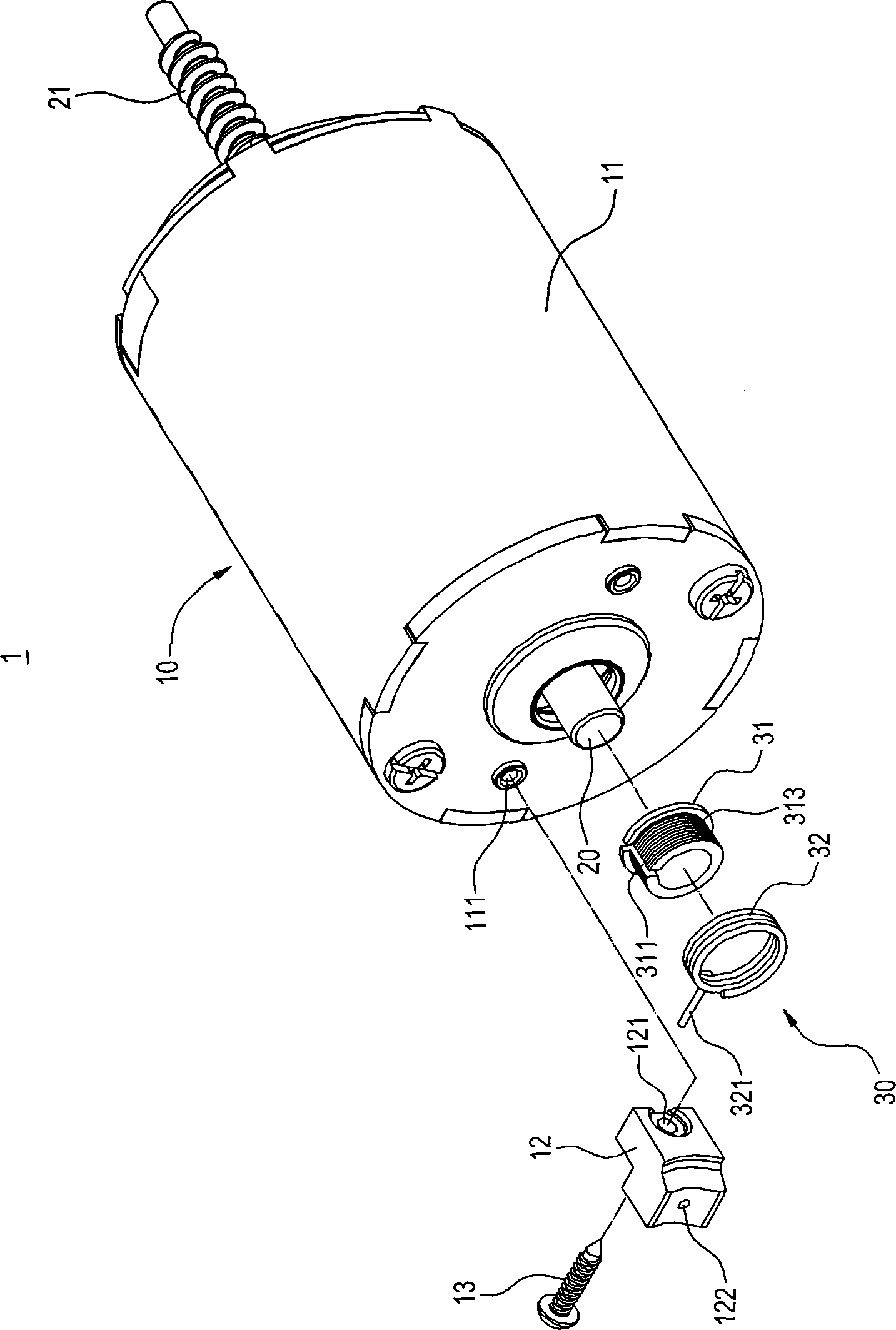
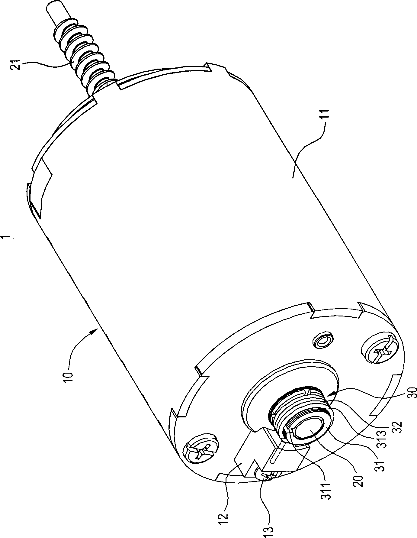
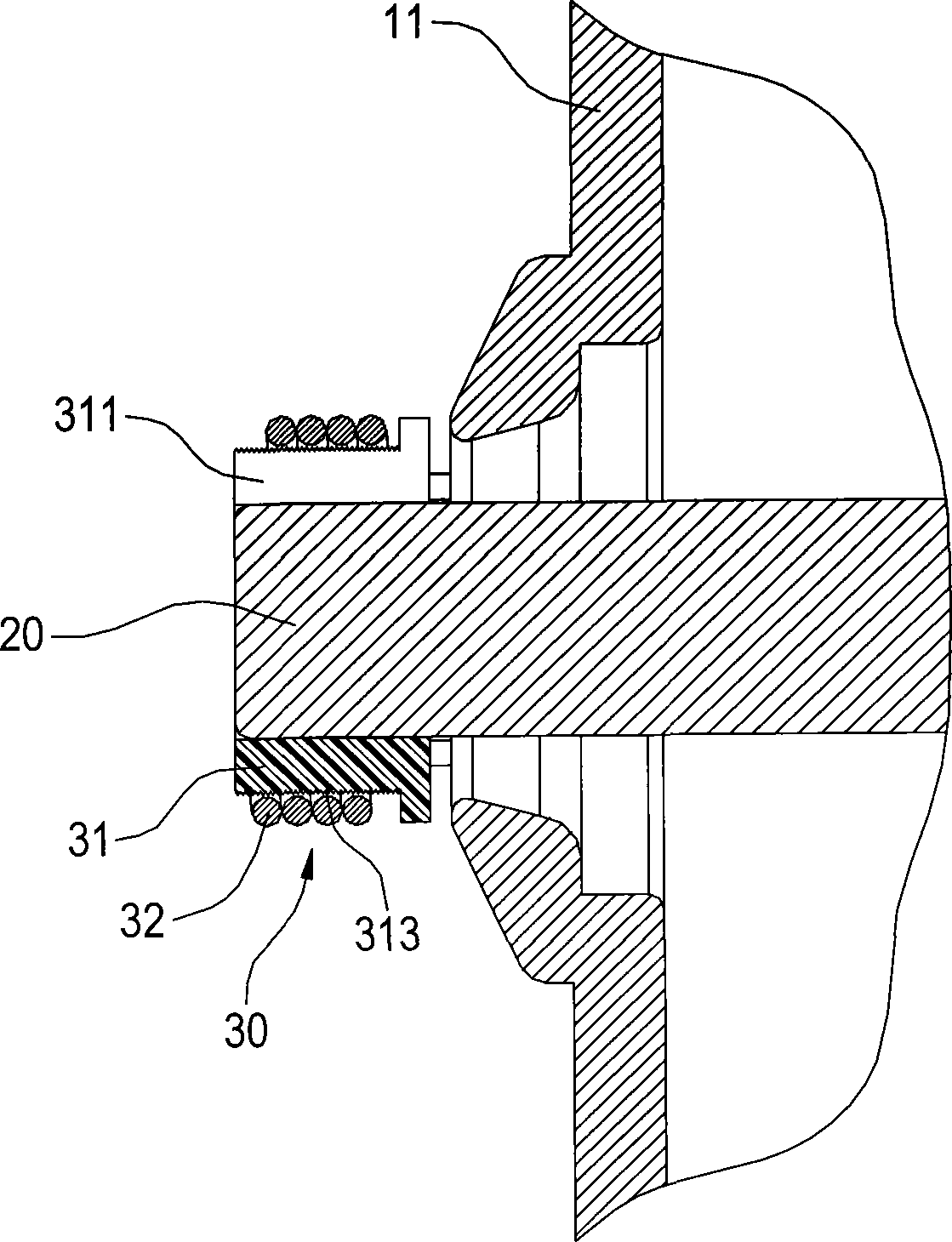
[0052] see Figure 1 to Figure 3 As shown, the present invention provides a motor with a braking deceleration mechanism for an actuator. The motor 1 mainly includes a body 10 , a rotating shaft 20 and a braking deceleration mechanism 30 .

[0053] The main body 10 is mainly composed of a cylindrical shell 11 , a rotor, a stator and a coil set (not shown) accommodated inside the shell 11 , and a plurality of screw holes 111 are provided on the rear end of the shell 11 . The body 10 of this embodiment also includes a fixing piece 12, which is roughly in the shape of a ladder, and has a through hole 121 and an insertion hole 122 on it, and the through hole 121 is used for a screw fixing component 13 to pass through and S...


PUM


Abstract

The invention discloses a motor with a braking and decelerating mechanism and for an actuating device. The motor comprises a body, a rotary shaft and the braking and decelerating mechanism, wherein the rotary shaft is penetratingly connected at the center of the body, the braking and decelerating mechanism comprises a frictional component and a spiral spring, the frictional component is connected on the peripheral edge of the rotary shaft in a sleeved manner, the spiral spring is elastically clamped on the periphery of the frictional component, one end of the spiral spring is positioned on the body, and the spiral spring can press the frictional component to brake the rotary shaft to decelerate when the rotary shaft rotates unidirectionally. Consequently, the motor with the braking and decelerating mechanism and for the actuating device is prolonged in service life due to low loss of the spiral spring, and good in braking and decelerating performance due to large contact area between the frictional component and the rotary shaft.

Description

technical field [0001] The invention relates to a motor for a linear actuator, in particular to a motor for an actuator with a braking deceleration mechanism. Background technique [0002] Linear Actuator (Linear Actuator) mainly uses motors, worms, worm gears and other drive components to drive a lead screw to rotate, and at the same time uses the lead screw to drive the telescopic tube screwed on it to linearly extend or retract. Because its structure and installation are simpler and more convenient than pneumatic and hydraulic cylinders, it has been widely used in hospital beds, electric chairs and other equipment, or in other fields that require expansion and contraction operations. [0003] Existing linear actuating devices such as European Patent Publication No. EP0662573B1 and PCT Patent Publication No. WO2004-027290A2 disclose, wherein the actuating device disclosed in the case of EP0662573B1 mainly includes a worm, a lead screw, and a screw fixed at one end of the l...

Claims


Application Information

Patent Timeline
Patent Type & Authority Patents(China)
IPC IPC(8): F16D59/02F16D49/20F16D65/06
Inventor 吴周欣
Owner 第一传动科技股ふん有限公司
Why Eureka
Try Eureka