A hinge structure with a signal transmission line

A signal transmission line and signal transmission technology, applied in the direction of two-part connection device, electrical components, coupling device, etc., can solve the problems of unusable RF coaxial cable, reduce wireless communication capability, RF impedance deviation, etc., to improve signal transmission performance , long service life, the effect of reducing radio frequency loss

Active Publication Date: 2018-06-22
SHANGHAI AMPHENOL AIRWAVE COMM ELECTRONICS CO LTD
View PDF9 Cites 0 Cited by
  • Summary
  • Abstract
  • Description
  • Claims
  • Application Information

AI Technical Summary

Problems solved by technology

The main performance of the RF coaxial line is that the radio frequency impedance has a great relationship with the size between two concentric metal conductors. Generally, it is not allowed to bend the RF coaxial line with a small radius or multiple times, so as to avoid the deviation of the radio frequency impedance caused by the size change of the metal conductor and reduce the wireless communication capability.
[0004] At present, there is a notebook computer whose LED display can rotate nearly 360° around the hinge relative to the keyboard main body, but all the cables passing through the hinge will rotate with the hinge, so the RF coaxial cable cannot be used
Thinner striplines have the opportunity to be used, but they have to endure the impact of high radio frequency loss on the wireless communication performance of laptops
At present, the antenna of this kind of notebook computer is only arranged on the host side of the keyboard, and there are many factors affecting the performance of the antenna.

Method used


Image

  • A hinge structure with a signal transmission line
  • A hinge structure with a signal transmission line
  • A hinge structure with a signal transmission line

Examples


Embodiment 1

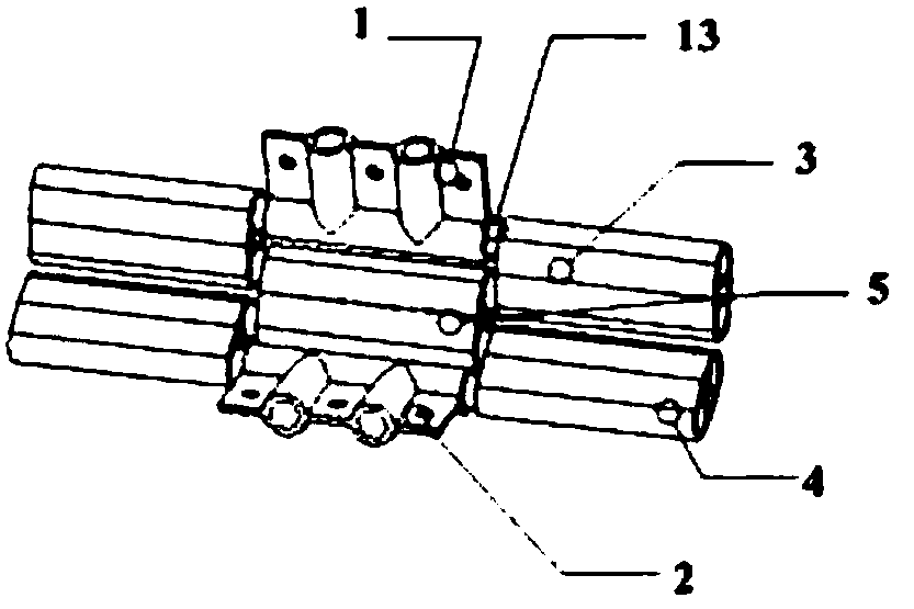
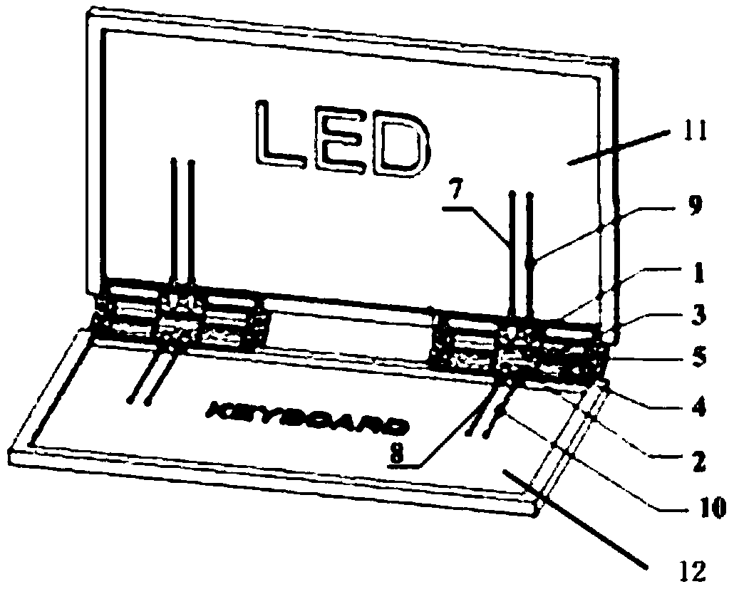
[0043] combine Figure 1-Figure 5 , the hinge structure with signal transmission line of the present invention is described in detail, as figure 1 Shown is a schematic diagram of its structure, including two rotor blades, namely the first rotor blade 1 and the second rotor blade 2, and the two rotor blades are connected by three rotor blade connectors, which are respectively the first rotor blade connector 3. The second rotating blade connecting piece 4 and the third rotating blade connecting piece 5 . In this embodiment, the first rotor blade connector 3 and the second rotor blade connector 4 respectively include two symmetrical parts, which are respectively located at the two ends of the first rotor blade 1 and the second rotor blade 2, so that two sets of signal signals can be realized. The signal of the first signal transmission line 7 is transmitted to the second signal transmission line 8 through the left hinge structure, and the signal of the third signal transmission ...

Embodiment 2

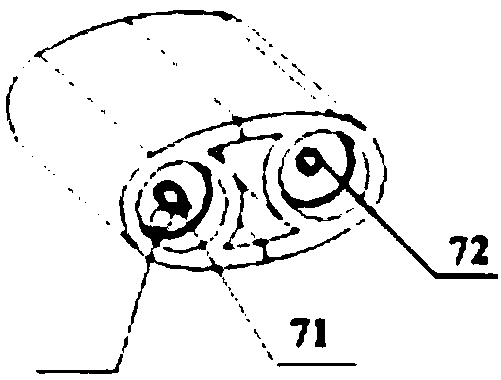
[0054] The difference between this embodiment and Embodiment 1 is that the first signal transmission channel of the first rotor blade connector 3 communicates with the second signal transmission channel through a U-shaped connector, and the third signal of the second rotor blade connector 4 The transmission channel and the fourth signal transmission channel are also communicated through a U-shaped connector. The structural diagram of the U-shaped connector is shown in Figure 6 shown. In this embodiment, an insulating layer 75 is provided on the outer side of the central transmission line 74 of the signal transmission line, and a metal plating layer 76 is provided on the outer side of the insulating layer 75 .

[0055] It should be understood that the above-mentioned embodiments do not limit the present invention, and different embodiments may only include the first rotor blade connector 3 and the second rotor blade connector 4, and the second signal of the first rotor blade c...


PUM


Abstract

The invention discloses a hinge structure with a signal transmission line. The hinge structure comprises at least two rotating vanes and two parallel rotating vane connecting pieces arranged between the two adjacent rotating vanes, i.e. a first rotating vane, a second rotating vane, a first rotating vane connecting piece and a second rotating vane connecting piece, wherein the first and second rotating vanes are connected through the first and second rotating vane connecting pieces in a rotating manner; each rotating vane connecting piece comprises at least two parallel signal transmission channels; the signal transmission channels in each rotating vane connecting piece are in S-shaped connection; a signal of a first unit connected with the first rotating vane can be transmitted into a second unit connected with the second rotating vane. According to the hinge structure with the signal transmission line, the signal transmission channels are designed as in the S-shaped connection, so that the signal transmission channels are perpendicular to a rotating direction, are namely parallel to the hinge structure, and are not likely to be bent along with bending of the hinge structure, influence on transmission performance of the signal transmission line is eliminated, and long service life is ensured.

Description

technical field [0001] The invention relates to a hinge structure, in particular to a hinge structure with a signal transmission line. Background technique [0002] A notebook computer usually includes two parts: an LED display part and a keyboard host, which are connected by a hinge. The location of the wireless communication antenna of the computer is generally hoped to be distributed on the top of the LED display, because it is easy to obtain better radio frequency performance. One end of the antenna is connected to the RF coaxial cable, and the RF coaxial cable passes through the hinge and is connected to the mainframe PCB at the keyboard main board end. [0003] RF coaxial cable is a kind of signal transmission line. Its structure is characterized by two concentric circular metal conductors, the two conductors are separated by insulating material, and the outer conductor is protected by insulating rubber wrapping. The main performance of the RF coaxial line is that th...

Claims


Application Information

Patent Timeline
Patent Type & Authority Patents(China)
IPC IPC(8): H01R24/38H02G3/18
CPCH01R24/38H02G3/18
Inventor 李立忠满方明
Owner SHANGHAI AMPHENOL AIRWAVE COMM ELECTRONICS CO LTD
Why Eureka
Try Eureka