Production equipment and production method of high-density fiber bundle micro-unit optical cable

A production method and micro-unit technology, applied in the field of optical fiber and cable manufacturing, can solve the problems affecting the optical cable sheath forming process, increasing the difficulty of the optical cable production process, poor roundness of the outer diameter of the optical cable, etc., to save raw materials, improve competitive advantages, The effect of high roundness

Active Publication Date: 2020-01-14
YANGTZE OPTICAL FIBRE & CABLE CO LTD
View PDF7 Cites 0 Cited by
  • Summary
  • Abstract
  • Description
  • Claims
  • Application Information

AI Technical Summary

Problems solved by technology

[0003] However, in the above-mentioned manufacturing process, the optical fiber has almost no structural excess length in the optical cable, and the strain of the optical fiber often exceeds the standard during the tensile test.
Usually, after the strain of the optical fiber exceeds the standard, it is considered to increase the diameter of the strength member or increase the number of auxiliary strength members, which will increase the cost of the optical cable on the one hand, and increase the difficulty of the production process of the optical fiber cable on the other hand.
In addition, embedding the strengthening member into the sheath will affect the forming process of the optical cable sheath, resulting in poor roundness of the outer diameter of the optical cable, and during the debugging of the production process, it is found that the larger the diameter of the strengthening member, the outer diameter of the optical cable will be affected. The larger it is, the existing production process conditions are difficult to make this structural optical cable round

Method used


Image

  • Production equipment and production method of high-density fiber bundle micro-unit optical cable
  • Production equipment and production method of high-density fiber bundle micro-unit optical cable
  • Production equipment and production method of high-density fiber bundle micro-unit optical cable

Examples


Embodiment Construction

[0028] It should be understood that the specific embodiments described here are only used to explain the present invention, not to limit the present invention.

[0029] It should be noted that, in the description of the present invention, the terms "horizontal", "vertical", "upper", "lower", "front", "rear", "left", "right", "vertical", The orientation or positional relationship indicated by "horizontal", "top", "bottom", "inner", "outer", etc. is based on the orientation or positional relationship shown in the drawings, and is only for the convenience of describing the present invention and simplifying the description, and It is not to indicate or imply that the device or element referred to must have a particular orientation, be constructed in a particular orientation, or operate in a particular orientation, and thus should not be construed as limiting the invention.

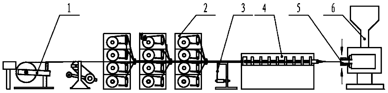
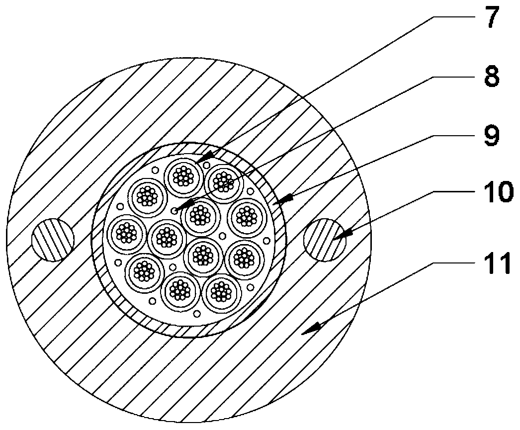
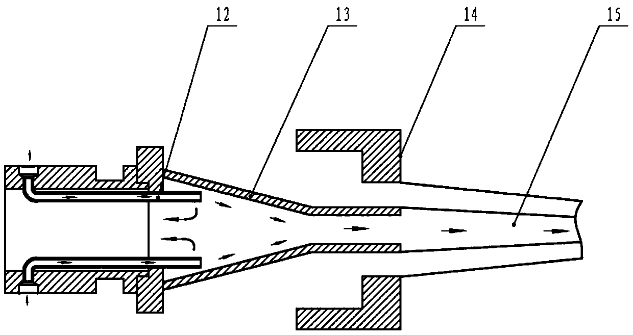
[0030] refer to Figure 1 to Figure 3 ( figure 1 and image 3 The direction indicated by the arrow in th...


PUM


Abstract

The invention discloses production equipment for a high-density optical fiber bundle micro unit optical cable. The production equipment comprises a reinforcing piece pay-off device, an optical fiber bundle micro unit pay-off device, a water blocking unit pay-off device, a stranding device and a jacket extruding device, wherein the inlet of the jacket extruding device is provided with a blowing device, an optical fiber bundle micro unit is released from the optical fiber bundle micro unit pay-off device and then enters the stranding device together with a water blocking yarn released from the water blocking unit pay-off device so as to be stranded, the stranded optical fiber bundle micro unit and an reinforcing piece released from the reinforcing piece pay-off device enter the jacket extruding device through the blowing device so as to extrude jackets. According to the production equipment for the high-density optical fiber bundle micro unit optical cable, before the micro unit bundle enters the jacket extruding device, the optical fiber bundle micro unit has a certain structure exceeded length, so that the tensile performance of the optical cable is improved; and the blowing deviceis added before the jacket extruding device, so as to ensure the cable round through the action of air flow.

Description

technical field [0001] The invention relates to the technical field of optical fiber cable manufacturing, in particular to a production equipment and a production method of a high-density optical fiber bundle micro-unit optical cable. Background technique [0002] With the evolution of optical communication networks towards large capacity and high speed, fiber optic cable technology is also continuously improving. How to further improve the utilization of pipeline resources, optimize the cable structure as much as possible without affecting the transmission efficiency and capacity, and increase the fiber density of the cable are the key issues of the fiber optic cable industry at this stage. At present, the method to increase the density of optical fibers in the industry is mainly to reduce the outer diameter of the sleeve unit and increase the number of sleeve units in the optical cable, thereby increasing the density of optical fibers in the cable. High-density optical fi...

Claims


Application Information

Patent Timeline
Patent Type & Authority Patents(China)
IPC IPC(8): G02B6/44
CPCG02B6/4479G02B6/4486
Inventor 段宏峰詹浩阮云芳胡海峰万冰熊壮
Owner YANGTZE OPTICAL FIBRE & CABLE CO LTD
Why Eureka
Try Eureka