
Electronic cable

A cable and outer tube technology, applied in the direction of insulated cables, cables, circuits, etc.

Active Publication Date: 2015-06-24
SONY COMPUTER ENTERTAINMENT INC
View PDF5 Cites 0 Cited by
  • Summary
  • Abstract
  • Description
  • Claims
  • Application Information

AI Technical Summary

Problems solved by technology

However, since the core wire made of a conductor such as copper does not elongate, when the outer tube elongates, a load is applied to the connecting portion where the core wire and the terminal are connected.

Method used


Image

  • Electronic cable
  • Electronic cable
  • Electronic cable

Examples


Embodiment Construction

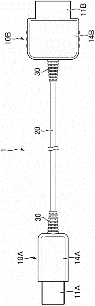
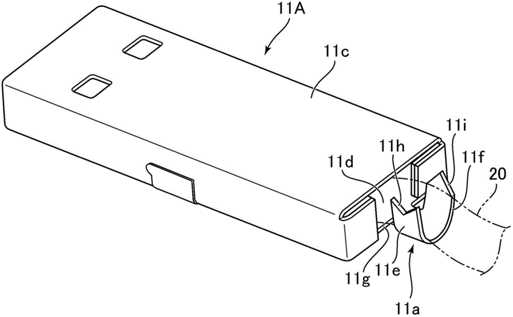
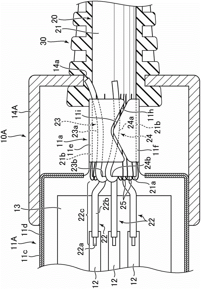
[0014] Hereinafter, one embodiment of the present invention will be described with reference to the drawings. figure 1 It is a top view of the cable 1 which concerns on embodiment of this invention. figure 2 It is a perspective view of a shielding box 11A included in the connector 10A provided at the end of the cable 1 . image 3 is a horizontal sectional view of the connector 10A.

[0015] The cable 1 is a cable for electrically connecting two electronic devices, such as a USB cable, an HDMI cable, a DVI cable, or a parallel interface cable (Centronics cable). Such as figure 1 As shown, the cable 1 has a cable body 20 and connectors 10A, 10B provided at both ends of the cable body 20 . The connectors 10A and 10B are plug connectors that are inserted into receptacle connectors provided in electronic equipment when the cable 1 is used. The connectors 10A, 10B of this example have different sizes, but may be the same connector. The connectors 10A and 10B have a function of...


PUM


Abstract

A cable main includes an outer tube, a core wire, and an assisting wire. The assisting wire is less stretchable than the outer tube. Connectors provided at ends of the cable main fasten ends of the assisting wire at ends of the outer tube so as to restrain the ends of the outer tube from moving in a stretch direction of the outer tube. According to this structure, even when the outer tube is stretched, a load applied to a connecting part between the core wire and a terminal of the connector can be reduced.

Description

technical field [0001] The invention relates to a cable for electrical connection between electronic devices. Background technique [0002] In the past, cables that electrically connect two electronic devices are being used. For example, the portable electronic device disclosed in US Patent Application Publication No. 2007 / 0202956 has a USB terminal and is connected to other electronic devices through a USB cable. [0003] Such a cable includes: a cable body having a plurality of core wires and an outer tube covering the core wires; and a connector provided at an end of the cable body. The connector has a metal box, and the end of the cable body is inserted into the inside of the box. The end of the core wire further extends from the end of the outer tube, and is welded to a terminal housed in the case. [0004] The outer tube is formed of a flexible and stretchable resin. Therefore, the cable main body of the outer tube may be stretched when it is bent or stretched in i...

Claims


Application Information

Patent Timeline
Patent Type & Authority Patents(China)
IPC IPC(8): H01R31/06H01R13/58
CPCH01R13/5816H01R13/5845H01B7/1825H01B7/223H01R13/567
Inventor 高桥圭久保田浩久铁地河原保
Owner SONY COMPUTER ENTERTAINMENT INC
Learn More