
Stick-shaped motor stator fixing structure with axial pretension force

A motor stator, pre-tension technology, applied in the magnetic circuit shape/style/structure, magnetic circuit static parts and other directions, can solve the aggravated interference situation, cannot further ensure the straight extension state of the stator 5, and the inaccurate way of the contact state, etc. question

Active Publication Date: 2014-09-24
HIWIN MIKROSYST
View PDF3 Cites 0 Cited by
  • Summary
  • Abstract
  • Description
  • Claims
  • Application Information

AI Technical Summary

Problems solved by technology

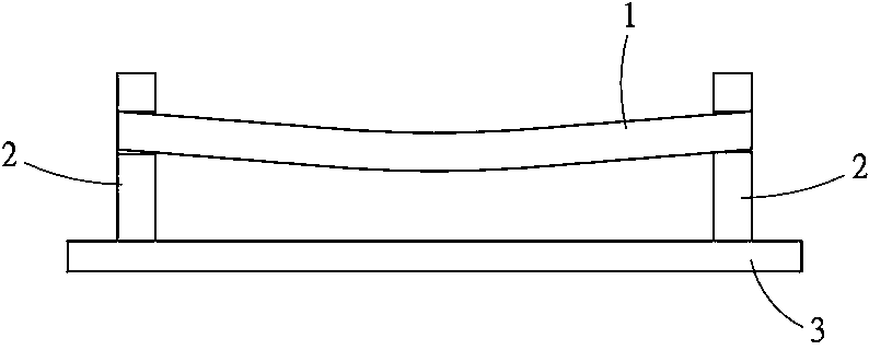
[0002] see figure 1 As shown, the well-known rod-shaped motor is based on a rod-shaped stator 1, providing the mover along the rod axis direction of the stator 1, and reciprocating sliding movement under the action of the magnetic field to provide power for industrial use , and the setting of the stator 1 is to divide the two fixed seats 2 on a metal base 3 as bridge piers, and then set the stator 1 bridge on the two fixed seats 2, so that the stator 1 is suspended on the base 3, however, in this way, the magnetic force generated by most of the magnets accommodated inside the stator 1 will make the stator 1 lean towards the direction of the base 3, and the effect of gravity makes it easy to derive the stator from the above-mentioned conventional technology 1 is bent in the direction of gravity, resulting in poor levelness, causing the mover to move on the stator 1, and the interference between the two is intensified, thus affecting the normal operation of the rod motor
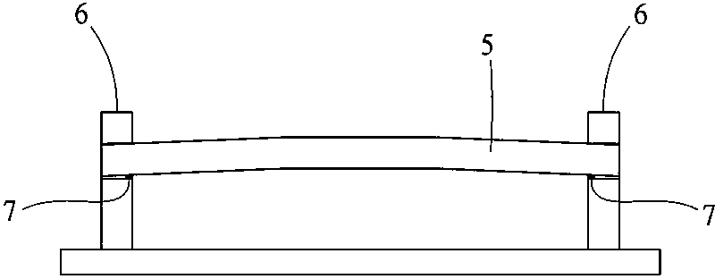
[0003] And in order to improve the deficiency of above-mentioned traditional technology, then as figure 2 In the disclosed technology, a thin metal plate 7 is further interposed between the stator 5 and the fixed seat 6, by providing the upward bending moment of the stator 5 in the direction of gravity, in order to offset the downward bending of the stator 5 caused by gravity and magnet attraction Although these technical contents can achieve the effect of maintaining the levelness of the stator 5, but because the method of changing the contact state between the stator 5 and the fixed seat 6 through the metal sheet 7 is not accurate, it is difficult to ensure whether the provided bending moment is enough, it is easy to produce insufficient or excessive situation, and the bending moment provided by it is only one-way, so it cannot further ensure the linear extension state of the stator 5 in the horizontal direction

Method used


Image

  • Stick-shaped motor stator fixing structure with axial pretension force
  • Stick-shaped motor stator fixing structure with axial pretension force
  • Stick-shaped motor stator fixing structure with axial pretension force

Examples


Embodiment Construction

[0018] Hereinafter, a preferred embodiment of the present invention will be cited and further described in conjunction with the accompanying drawings.

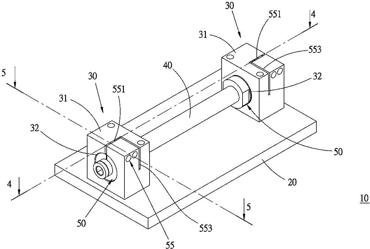
[0019] see Figure 3 to Figure 5 As shown, the rod-shaped motor stator fixing structure 10 with axial pretension provided in a preferred embodiment of the present invention includes a base 20 , two abutments 30 , a stator 40 and a pretension group 50 .

[0020] The base 20 is generally in the shape of a rectangular plate and is used as a basis for other components.

[0021] Each of the plinths 30 is spaced apart from each other and is respectively arranged on the two ends of the long axis of the upper side seat surface of the base, and is symmetrical to each other, and has a block-shaped seat body 31, which is attached and fixed on the bottom side end surface. On the base 20 , a fixing hole 32 runs through the seat body 31 , and makes the fixing holes 32 of the podiums 30 coaxially correspond to each other.

[0022] The stat...


PUM


Abstract

The invention relates to a stick-shaped motor stator fixing structure with an axial pretension force. The structure comprises a base, two pier bases, a rod-shaped stator and a prestressing force group, the two pier bases are separated from each other, each pier base includes a base body and a fixing hole, the base body is arranged on the upper side base surface of the base, the fixing hole penetrates through the base body, two ends of a rod shaft respectively penetrate through one corresponding fixing hole, so that the stator is in a bridge connection between the pier bases, the prestressing force group includes two abutting surfaces, two pushing portions and two combining portions, the two abutting surfaces are located at two ends of the rod shaft of the stator respectively and correspond to each other oppositely, the two pushing portions are arranged on the stator in a sliding mode respectively and located between the stator and the hole walls of the fixing hole which the stator penetrates through, mutually reverse one ends of the two pushing portions are respectively abutted to corresponding abutting surfaces, the two combining portions are used for mutually combining each pushing portion with one corresponding base body, the pushing portions can be used to push and abut to the corresponding abutted abutting surfaces in mutually reverse directions, the axial pretension force can be exerted on the stator, a linear state of the stator can be guaranteed, and the exerted pretension force can be adjusted according to conditions of different stators and active cells.

Description

technical field [0001] The invention relates to a rod motor, in particular to a rod motor stator fixing structure with axial pretension. Background technique [0002] see figure 1 As shown, the well-known rod-shaped motor is based on a rod-shaped stator 1, providing the mover along the rod axis direction of the stator 1, and reciprocating sliding movement under the action of the magnetic field to provide power for industrial use , and the setting of the stator 1 is to divide the two fixed seats 2 on a metal base 3 as bridge piers, and then set the stator 1 bridge on the two fixed seats 2, so that the stator 1 is suspended on the base 3, however, in this way, the magnetic force generated by most of the magnets accommodated inside the stator 1 will make the stator 1 lean towards the direction of the base 3, and the effect of gravity makes it easy to derive the stator from the above-mentioned conventional technology 1 bends in the direction of gravity, resulting in poor level...

Claims


Application Information

Patent Timeline
Patent Type & Authority Patents(China)
IPC IPC(8): H02K1/18
Inventor 张维麟黄柏盛
Owner HIWIN MIKROSYST
Learn More