A communication method and system combining power line communication and optical communication

A technology of power line communication and communication method, which is applied in the field of communication method and system combining power line communication and optical communication, which can solve problems such as complex power line structure and signal reflection, and achieve broad market prospects, convenient access, and high-speed broadband The effect of signal transmission

Active Publication Date: 2015-12-02
TSINGHUA UNIV +1
View PDF4 Cites 0 Cited by
  • Summary
  • Abstract
  • Description
  • Claims
  • Application Information

AI Technical Summary

Problems solved by technology

[0007] To realize a communication system combining power line communication and optical communication, there are some problems: 1. How to realize the seamless integration of the two communication systems, and realize the mutual conversion of electrical signals and optical signals conveniently and quickly; According to the characteristics and business requirements, choose the transmission mode reasonably, and improve the reliability of transmission as much as possible
In the optical communication system, multiple LED light sources are often used to achieve good lighting effects, and the indoor environment also has a reflection effect on the lighting, so the multipath effect has a significant impact on the indoor LED optical communication system; the line structure of the power line Complicated, the signal can reach the terminal through multiple paths, and there will be signal reflection at the load, which makes the power line communication also have serious multipath effects

Method used


Image

  • A communication method and system combining power line communication and optical communication
  • A communication method and system combining power line communication and optical communication
  • A communication method and system combining power line communication and optical communication

Examples


Embodiment 1

[0050] This embodiment presents the application of the communication method combining power line communication and optical communication proposed by the present invention in a downlink communication system oriented to broadband digital terrestrial broadcasting. The system requires downlink standard definition digital TV broadcasting service within 8MHz bandwidth. The method flow and transfer modes involved are detailed below:

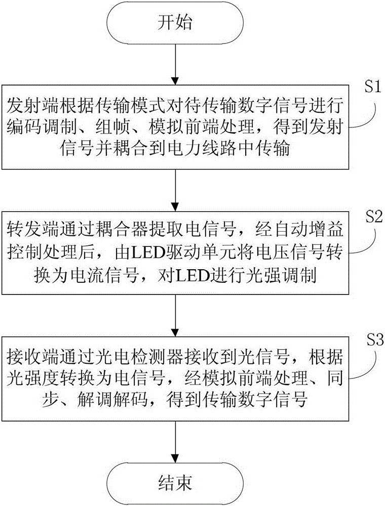
[0051] S1. The transmitting end performs coding modulation, framing, and analog front-end processing on the digital signal to be transmitted according to the predetermined transmission mode, to obtain the transmitted signal and couple it to the power line for transmission;

[0052] The system bandwidth is 8MHz, the channel bandwidth is also 8MHz, the working frequency band of the power line communication system is 2-10MHz, and the LED flashing speed is 10MHz. Referring to the Chinese digital TV terrestrial broadcasting standard DTMB, the analog front-e...

Embodiment 2

[0065] This embodiment presents the application of the communication method combining power line communication and optical communication proposed by the present invention in a duplex communication system oriented to broadband wireless digital communication. In this duplex communication system, the uplink is realized by WIFI, and the downlink is realized by a combination of power line communication and optical communication. It is required to provide downlink high-definition digital TV services within a 30MHz bandwidth, and the involved method flow and transmission mode are detailed as follows:

[0066] S1. The transmitting end performs coding modulation, framing, and analog front-end processing on the digital signal to be transmitted according to the predetermined transmission mode, to obtain the transmitted signal and couple it to the power line for transmission;

[0067] The system bandwidth is 30MHz, the channel bandwidth is also 30MHz, the working frequency band of the pow...

Embodiment 3

[0082] This embodiment presents the application of the communication method combining power line communication and optical communication proposed by the present invention in a duplex communication system oriented to indoor broadband multi-service digital communication. In the duplex communication system, the uplink is realized by power line communication, and the downlink is realized by combining power line communication and optical communication. It is required to provide smart home and Internet of Things services within a 48MHz bandwidth, and the methods, procedures and transmission modes involved are detailed as follows:

[0083] S1. The transmitting end performs coding modulation, framing, and analog front-end processing on the digital signal to be transmitted according to the predetermined transmission mode, to obtain the transmitted signal and couple it to the power line for transmission;

[0084] The system bandwidth is 48MHz, the channel bandwidth is also 48MHz, the wo...


PUM


Abstract

The invention provides a communication method with combination of electric wire communication and light communication. The communication method comprises the following steps that: S1, a transmitting terminal performs code modulation, framing and analog front end treatment on a digital signal to be transmitted according to a predetermined transmission mode, so that a transmitting signal is obtained and coupled to an electric power circuit for transmission; S2, a transfer terminal extracts an electric signal through a coupler and then delivers the electric signal to a light emitting diode (LED); after the automatic gain control process, a voltage signal is converted to a current signal by an LED driving unit to perform light intensity modulation on the LED; S3, a receiving terminal receives the light signal through a photoelectric detector and then converts the light signal to an electric signal according to the light intensity; the transmission digital signal is obtained through the analog front end process, the synchronization, demodulation and decoding. By adopting a generic technology, the seamless combination of a power line network and the LED light communication is achieved, two signals are combined into one; the electric signal transmitted by the electric power circuit can be emitted out in a manner of wireless light communication through the LED without signal regeneration, so that the wideband high-speed signal transmission is implemented.

Description

technical field [0001] The invention belongs to the technical field of communication, and in particular relates to a communication method and system combining power line communication and optical communication. Background technique [0002] With the rapid development of communication technology, the contradiction between rapidly expanding wireless communication service requirements and spectrum resources is increasingly intensified. Exploring new spectrum resources has become a hot issue in the field of wireless communication today. As an emerging wireless communication technology that uses light waves as the information transmission carrier, optical communication has the advantages of wide transmission frequency bandwidth, large communication capacity, safety and environmental protection, no electromagnetic interference, and no need to occupy existing spectrum resources. It has attracted much attention in recent years. [0003] Since the 1990s, the rapid development of LED ...

Claims


Application Information

Patent Timeline
Patent Type & Authority Patents(China)
IPC IPC(8): H04B3/54H04L1/06H04L27/26H04Q11/00
Inventor 宋健杨昉颜克茜王劲涛张超李晓
Owner TSINGHUA UNIV
Why Eureka
Try Eureka