Direct-current level detection circuit between high-speed signal line ports, system comprising the circuit and manufacturing method and application method thereof

一种检测电路、连接端口的技术,应用在检测可插接式模块与相应插槽间连接状态领域,能够解决MOD-ABS被占用等问题,达到提高安装精度、扩展功能性、广泛应用前景的效果

Active Publication Date: 2015-05-20
SOURCE PHOTONICS CHENGDU
View PDF6 Cites 2 Cited by
  • Summary
  • Abstract
  • Description
  • Claims
  • Application Information

AI Technical Summary

Problems solved by technology

However, with the recent development of module applications, MOD-ABS may be occupied

Method used


Image

  • Direct-current level detection circuit between high-speed signal line ports, system comprising the circuit and manufacturing method and application method thereof
  • Direct-current level detection circuit between high-speed signal line ports, system comprising the circuit and manufacturing method and application method thereof
  • Direct-current level detection circuit between high-speed signal line ports, system comprising the circuit and manufacturing method and application method thereof

Examples


Embodiment 2

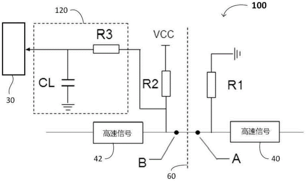
[0061] Such as Figure 5 As shown, the DC level detection circuit 300 between the high-speed signal line connection ports A and B includes a first resistor R1 , a second resistor R2 , a low-pass filter 320 , and a signal detection port 330 . One end or terminal of the first resistor R1 is connected to the second port B of the high-speed signal line 342 , and the other end or terminal of the resistor R1 is grounded. One end or terminal of the second resistor R2 is connected to the first port A of the high-speed signal line 340 , and the other end or terminal of the resistor R2 is grounded and connected to the DC voltage source VCC. The low-pass filter 320 is connected (eg, at the output end) to the signal detection port 330 , and the other end (eg, input) of the low-pass filter 320 is connected to the first port A of the high-speed signal line 340 . The resistance of the second resistor R2 is 5 or 6 times the resistance of the resistor R1. When the ports A and B are not conne...

Embodiment 300

[0064] The exemplary embodiment 300 utilizes one or more ports for powering and signal detection functions of the pluggable module. In typical embodiments the 300 operates over Figure 1-2 While the exemplary embodiment 10 is slightly more complex (e.g., pluggable modules must be powered), this design also simplifies the design and operation of hardware protection slots (e.g., host devices) and enables module manufacturers to More functions are integrated in the module and reduce the burden on the manufacturer of the hardware containing the socket.

[0065] involves and uses Figure 4 The method shown for the level and / or connection status detection circuit is also applicable to the Figure 5 The level detection circuit 300 is shown.

[0066] The above detection circuits 10, 100 and 300 are all suitable for detecting the connection status of high-speed signal line ports in various communication devices, including optical, electrical or photoelectric devices. The above dete...


PUM


Abstract

The invention discloses a direct-current level detection circuit between high-speed signal line ports, a system comprising the circuit and a manufacturing method and an application method thereof. Each port corresponding to a high-speed signal line contains a resistor, and resistance value of one resistor is higher than that of the other one. The resistor having a lower resistance value is connected to the ground. The resistor having a larger resistance value is connected to a direct-current voltage source, a lowpass filter and a signal detection port, and therefore, both ports of the high-speed signal line are in a connected state. Change of the level state will be detected by the signal detection ports. Detection of the high-speed signal line in a connected state is realized in the circuit, which does not affect transmission of high-speed signal and is suitable for various circuits, particularly for pluggable modules and corresponding slots. Therefore, multiplex functions of the signal ports are realized by the circuit, accuracy degree of module installation is increased, and compatibility of pluggable modules is improved.

Description

technical field [0001] The invention relates to the field of communication, in particular to the field of hardware detection of optical communication devices. More specifically, the embodiments of the present invention are applicable to a circuit and a method for detecting a connection state between a pluggable module and a corresponding slot by using a port as a signal line. Background technique [0002] At present, in order to facilitate assembly and disassembly, a large number of socket interface designs are adopted between pluggable modules and main boards in the electrical communication field. The interface of the pluggable module adopts the plug corresponding to the slot, which is the so-called "golden finger" design. "Gold finger" refers to the contact portion of the socket receptacle, which consists of multiple conductive metal contacts (specifically gold). These contacts are arranged and / or displayed like fingers, so they are called "golden fingers". The "golden ...

Claims


Application Information

Patent Timeline
Patent Type & Authority Applications(China)
IPC IPC(8): H04B10/07H04B17/00
CPCG01R31/69G06F2101/00H01L21/00H01L2221/00
Inventor 蔡升志魏秋明黄远军许远忠
Owner SOURCE PHOTONICS CHENGDU
Why Eureka
Try Eureka