Address allocation method and host base station
An allocation method and address technology, applied in wireless communication, network data management, transmission system, etc., can solve address allocation problems, do not support PGW relocation and other problems
- Summary
- Abstract
- Description
- Claims
- Application Information
AI Technical Summary
Problems solved by technology
Method used
Image
Examples
Embodiment 1
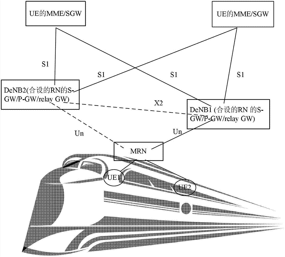
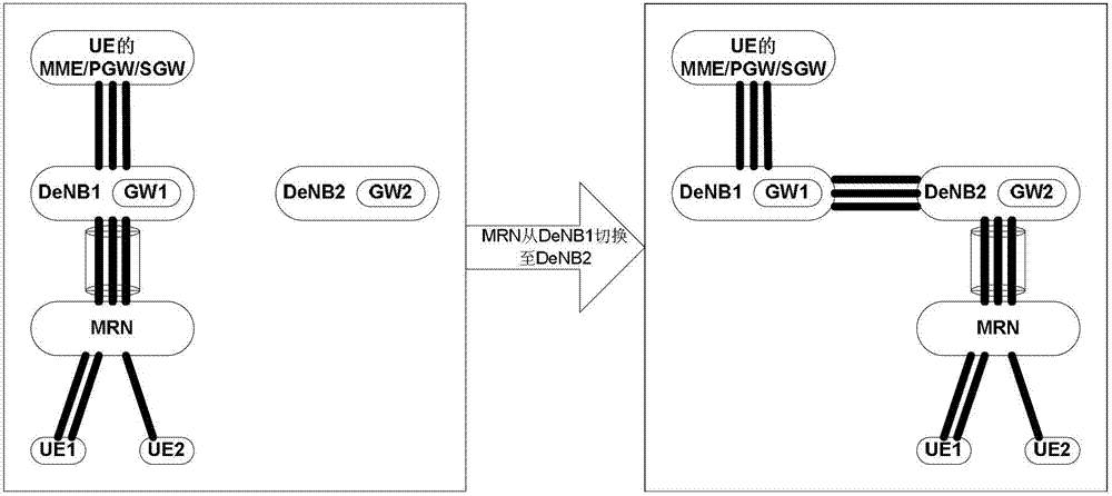
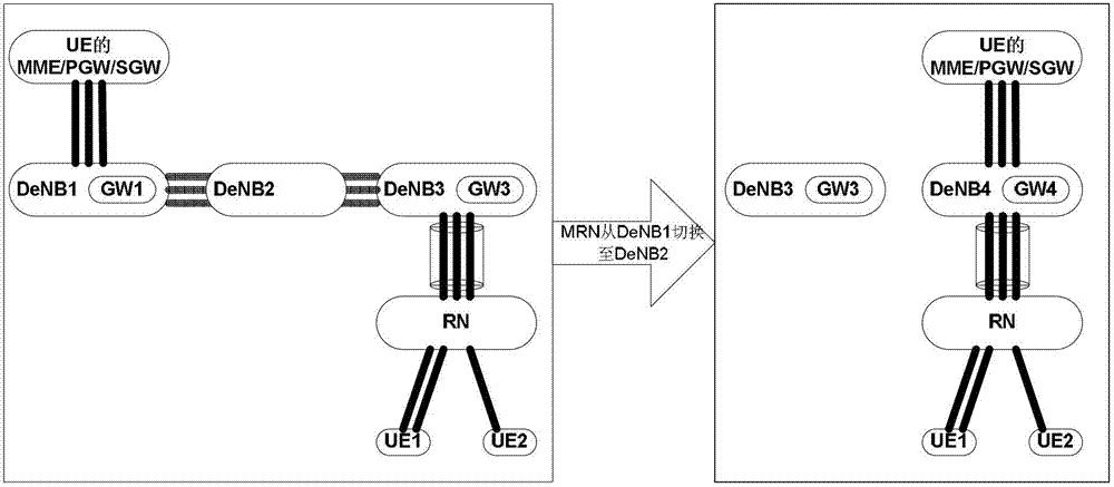
[0127] This embodiment describes a method in which the source DeNB sends the first IP address allocation auxiliary information to the target DeNB through an X2 interface message, and the target DeNB allocates an IP address during the handover preparation process. Figure 4 The flow of this embodiment is described. In this embodiment, the source S-GW and the source P-GW of the MRN may be built in the source DeNB, or may not be located in the source DeNB, but built in the initial DeNB (initial DeNB).
[0128] Step 401: The MRN detects the signal of the target DeNB cell during the measurement process, and triggers a measurement report event to send a measurement report to the source DeNB. After the source DeNB determines that the MRN needs to be handed over to the target DeNB, it determines that there is an X2 interface with the target DeNB, And after the handover, the MRN does not need to replace the MME, the source DeNB initiates an X2 handover for the MRN, and the source DeNB ...
Embodiment 2
[0147] This embodiment describes a method in which the target DeNB obtains auxiliary IP address allocation information from the source DeNB and MME through X2 interface messages and S11 interface messages, and the target DeNB allocates IP addresses during session creation. Figure 5 The flow of this embodiment is described. In this embodiment, the source SGW and the source PGW of the MRN may be built in the source DeNB, or may not be located in the source DeNB, but built in the initial DeNB (initial DeNB).
[0148] Step 501: The MRN detects the signal of the target DeNB cell during the measurement process, and triggers a measurement report event to send a measurement report to the source DeNB. After the source DeNB determines that the MRN needs to be handed over to the target DeNB, it determines that there is an X2 interface with the target DeNB. And after the handover, the MRN does not need to replace the MME, then the source DeNB initiates an X2 handover for the MRN, and the...
Embodiment 3
[0165] This embodiment describes the method for the target DeNB to allocate an IP address during the handover preparation process in the S1 handover. Figure 6 The procedure described in this example is described. In this embodiment, the source SGW and the source PGW of the MRN may be built in the source DeNB, or may not be located in the source DeNB, but built in the initial DeNB (initial DeNB).
[0166] Step 601: The MRN detects the signal of the target DeNB cell during the measurement process, and triggers a measurement report event to send a measurement report to the source DeNB. After the source DeNB determines that the MRN needs to be handed over to the target DeNB, it determines that there is no X2 interface with the target DeNB , or the MRN needs to replace the MME after the handover, the source DeNB initiates an S1 handover for the MRN, and the source DeNB sends an S1 interface handover request (handover required) message to the source MME of the MRN, the handover req...
PUM
 Abstract
Description
Claims
Application Information
 - R&D
- Intellectual Property
- Life Sciences
- Materials
- Tech Scout
- Unparalleled Data Quality
- Higher Quality Content
- 60% Fewer Hallucinations
Browse by: Latest US Patents, China's latest patents, Technical Efficacy Thesaurus, Application Domain, Technology Topic, Popular Technical Reports.
© 2025 PatSnap. All rights reserved.Legal|Privacy policy|Modern Slavery Act Transparency Statement|Sitemap|About US| Contact US: help@patsnap.com


