Sole structure for shoe
A technology for structures and shoes, applied in soles, footwear, applications, etc., can solve the problems of large energy loss and achieve the effect of reducing energy loss and smooth running
- Summary
- Abstract
- Description
- Claims
- Application Information
AI Technical Summary
Problems solved by technology
Method used
Image

Examples
Embodiment 1
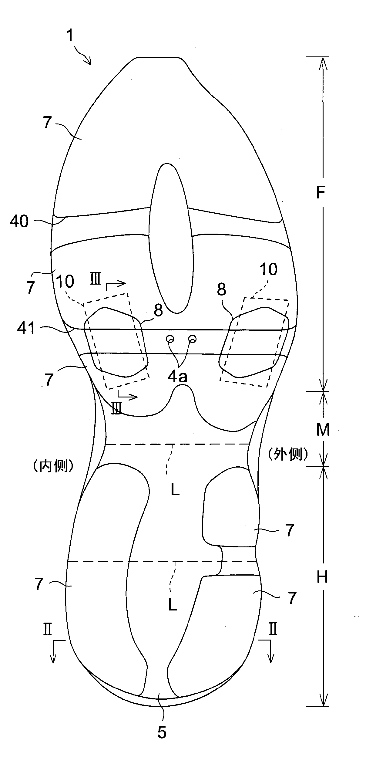
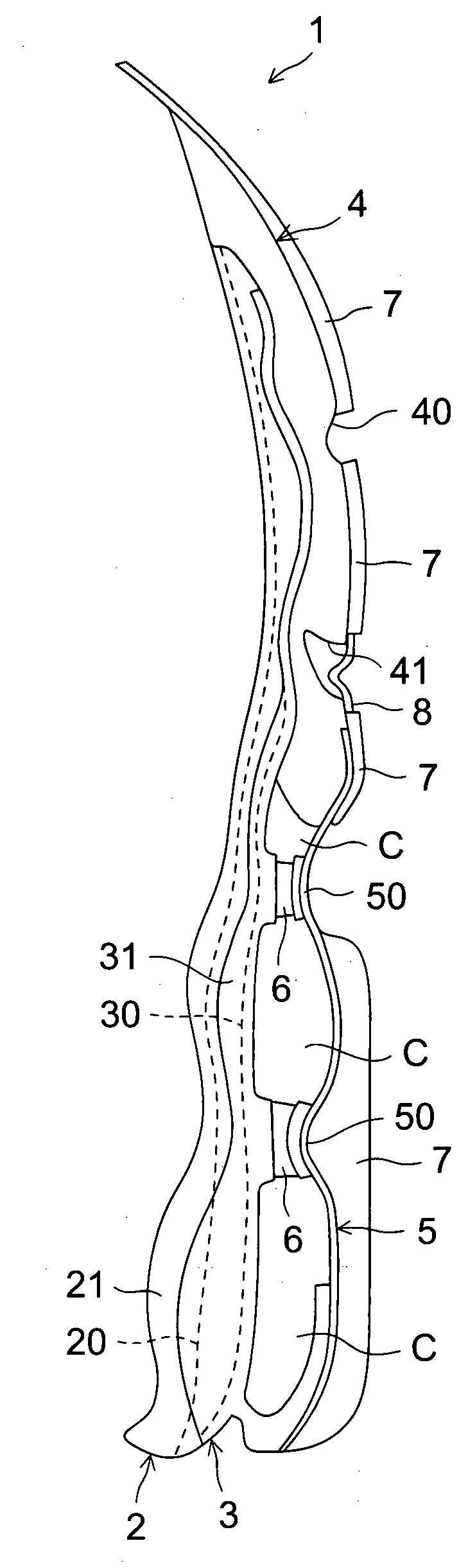
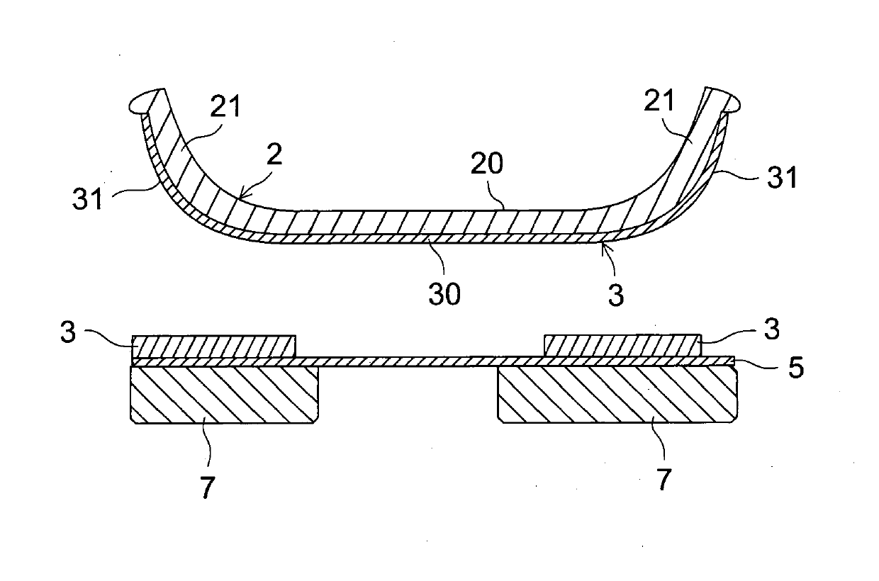
[0125] Figure 1A to Figure 7C The shoe sole structure of the first embodiment of the present invention is shown. Such as Figure 1A and Figure 1B As shown, the sole structure 1 includes: an upper midsole 2 made of a soft elastic member, which extends from the heel H of the shoe to the forefoot F through the midfoot M in the front-rear direction; the hard elastic member The upper plate 3 is fixed on the lower part of the upper middle sole 2, and extends from the heel H of the shoe to the forefoot F through the middle foot M in the front-rear direction; the lower middle sole made of soft elastic member 4. The lower midsole 4 is fixedly connected to the lower part of the upper plate 3, and is mainly arranged on the forefoot part F of the shoe; and the lower plate 5 made of a hard elastic member, which is mainly from the heel part H of the shoe to the center The foot M extends in the front-rear direction, and its front end is fixed to the lower part of the sole 4 in the lower...
Embodiment 2
[0191]In the above-mentioned first embodiment, the case where the groove 41 formed in the sole 4 in the lower part has an inverted V-shaped cross-sectional shape was described as an example, but the application of the present invention is not limited thereto. The cross-sectional shape of the groove 41 can also be an inverted U shape or an arc shape (ie, a flat inverted U shape). As the groove 41 , any shape other than the above can be adopted as long as it is a groove shape opening downward.
[0192] In addition, regardless of the cross-sectional shape of the groove 41, the bending restricting member 10 arranged in the groove 41 is bent upward because of the upper curved portion 10a bent upward in the groove 41, and the upper curved portion 10a is not fixed. on the bottom wall of the groove 41. In addition, ideally, the bending limiting member 10 is far away from the wall surface of the groove 41 and is not fixed to the wall surface of the groove 41 .
Embodiment 3
[0194] In the above-mentioned first embodiment, the case where the cross-sectional shape of the bending restricting member 10 in the front-rear direction of the sole was described as an example was described, but the cross-sectional shape of the bending restricting member 10 may be in an inverted U-shape. Or arc-shaped (that is, flat inverted U-shaped). In addition, various shapes can be adopted according to the cross-sectional shape of the groove 41 of the lower middle sole 4 and the like.
[0195] In addition, as bending limiting members such as Figure 8 As shown, there may be a lower curved portion 10'a bent downward in a V-shape or a U-shape. In this case, the elastic cover member 8' covering the lower curved portion 10'a of the bend restricting member 10' from below may also have a curved shape along the curved shape of the bend restricting member 10'. In addition, in Figure 8 In , the same symbols as those in the above-mentioned embodiments represent the same or cor...
PUM
 Abstract
Description
Claims
Application Information
 - R&D
- Intellectual Property
- Life Sciences
- Materials
- Tech Scout
- Unparalleled Data Quality
- Higher Quality Content
- 60% Fewer Hallucinations
Browse by: Latest US Patents, China's latest patents, Technical Efficacy Thesaurus, Application Domain, Technology Topic, Popular Technical Reports.
© 2025 PatSnap. All rights reserved.Legal|Privacy policy|Modern Slavery Act Transparency Statement|Sitemap|About US| Contact US: help@patsnap.com