Tail breaking tool of turbine guider

A turbine guider and tool technology, which is applied in the direction of manufacturing tools, metal processing, metal processing equipment, etc., can solve the problem that ordinary calipers cannot accurately control the amount of deformation, etc.

Active Publication Date: 2014-12-24
CHINA AVIATION POWER MACHINE INST
View PDF5 Cites 0 Cited by
  • Summary
  • Abstract
  • Description
  • Claims
  • Application Information

AI Technical Summary

Problems solved by technology

[0003] The purpose of the present invention is to provide a turbine guider tail breaking tool that can accurately control the deformation of the guider blade trailing edge, so as to solve the problem of repeated adjustments caused by the inability of ordinary calipers to accurately control the deformation

Method used


Image

  • Tail breaking tool of turbine guider
  • Tail breaking tool of turbine guider
  • Tail breaking tool of turbine guider

Examples


Embodiment Construction

[0016] The present invention will be described in detail below with reference to the accompanying drawings and examples.

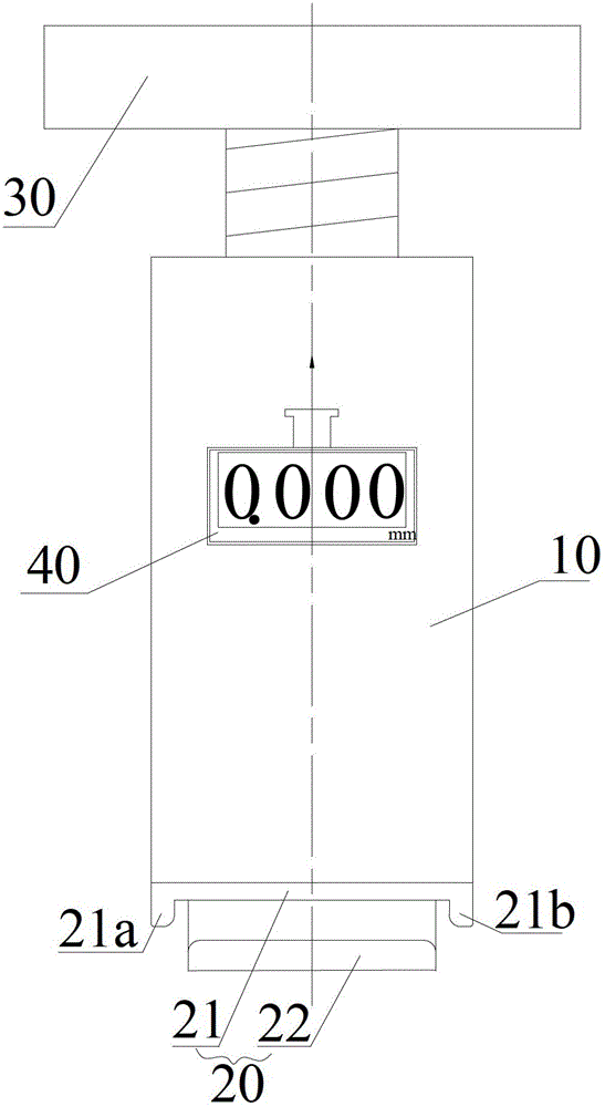
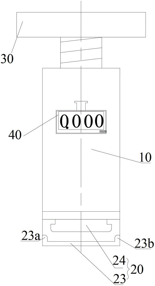
[0017] Such as figure 1 As shown, according to the first embodiment of the present invention, the tail breaking tool of the turbine guider includes a fixing sleeve 10, a tail breaking jig 20 provided at the first end of the fixing sleeve 10, and a tail breaking jig 20 arranged at the second end of the fixing sleeve 10 so as to break off the tail. The rotary mechanism 30 clamped by the tail clamp 20 ; the digital displacement measuring device 40 for measuring and displaying the clamping amount of the tail clamp 20 is also provided on the fixed sleeve 10 . The tail breaking tool of the turbine guider of the present invention, by setting the digital displacement measuring device 40 on the fixed sleeve 10 to measure and display the clamping amount of the tail breaking fixture 20, can be clamped according to the tail breaking fixture during the tail breaking op...


PUM


Abstract

The invention provides a tail breaking tool of a turbine guider. The tail breaking tool comprises a fixing sleeve, a tail breaking fixture and a rotary mechanism, wherein the tail breaking fixture is arranged at the first end of the fixing sleeve, the rotary mechanism is arranged at the second end of the fixing sleeve and is used for clamping the tail breaking fixture, and the fixing sleeve is also provided with a digital displacement measurement device which is used for measuring and displaying the clamping quantity of the tail breaking fixture. According to the tail breaking tool of the turbine guider, provided by the invention, by arranging the digital displacement measurement device which is used for measuring and displaying the clamping quantity of the tail breaking fixture on the fixing sleeve, the deformation of a tail edge of a blade of the guider can be accurately controlled according to the clamping quantity of the tail breaking fixture when in tail breaking operation, and the problem that the regulation needs to be carried out repeatedly due to excessive deformation can be avoided.

Description

technical field [0001] The invention relates to the field of engine assembly and debugging tools, in particular to a turbine guide tail breaking tool. Background technique [0002] Due to manufacturing deviations in the production process of various engine components, the performance of the complete machine cannot meet the design requirements after assembly, and engine performance adjustment is required. The most effective method is to adjust the throat area of ​​the turbine guide. At present, grinding the turbine guide is generally used. The way at the blade throat, the way the turbine guide blades are grouped, or the tail breaking method. The tail-bending method to adjust the throat area of ​​the turbine guide generally uses external force to deform the trailing edge of the blade to change the throat area of ​​the turbine guide. Because this method will not damage the anti-oxidation and anti-corrosion layer on the surface of the turbine guide when adjusting the throat are...

Claims


Application Information

Patent Timeline
Patent Type & Authority Patents(China)
IPC IPC(8): B23P19/00
Inventor 曾飞宋玉琴卢聪明
Owner CHINA AVIATION POWER MACHINE INST
Why Eureka
Try Eureka