Ball compensators for pipe connections

A compensator and pipeline technology, which is applied to expansion compensation devices for pipelines, pipes/pipe joints/pipes, pipe components, etc., and can solve the problem that the sealing ring is heavily loaded, cannot be installed and constructed, and the height of the overall structure is increased, etc. problems, to ensure the sealing effect, prevent liquid leakage, and achieve the effect of small installation space

Active Publication Date: 2015-12-09
SICE ELECTRIC POWER EQUIP
View PDF7 Cites 0 Cited by
  • Summary
  • Abstract
  • Description
  • Claims
  • Application Information

AI Technical Summary

Problems solved by technology

[0003] Patent No. 201120559664.3 "A Spherical Compensator" discloses a spherical compensator that installs a sealing ring on the radially outer side of the sphere. Due to the small contact area of ​​the sealing ring, the load per unit area of ​​the sealing ring is relatively large. Easily damaged, causing leakage
[0004] Patent No. 200820300623.X "Rotary Joint" also discloses a structure of a spherical compensator, which uses an axial spherical sealing ring to seal the rotary joint, but due to the use of an integral shell, the floater is installed in the shell, Therefore, the structure is complicated and the installation is inconvenient. At the same time, it is necessary to increase the pre-tension spring to effectively ensure the sealing effect of the spherical sealing ring. Moreover, due to the increase of the pre-tension spring, the height of the overall structure is significantly increased. For a compact installation position, Not easy to install or even impossible to install and construct
In addition, due to the gap between the sliding bearing and the inner wall of the housing, radial slippage can occur, which will easily cause wear between the spherical sealing ring and the sealing ring, resulting in oil leakage
However, in the installation and use of existing pipelines, sometimes a structure that does not occur radial slippage but requires a component to meet the requirements of axial swing and axial bidirectional displacement, then this patented structure is not necessary. suitable for the above requirements

Method used


Image

  • Ball compensators for pipe connections
  • Ball compensators for pipe connections
  • Ball compensators for pipe connections

Examples


Embodiment Construction

[0021] The present invention will be described in detail below in conjunction with the accompanying drawings.

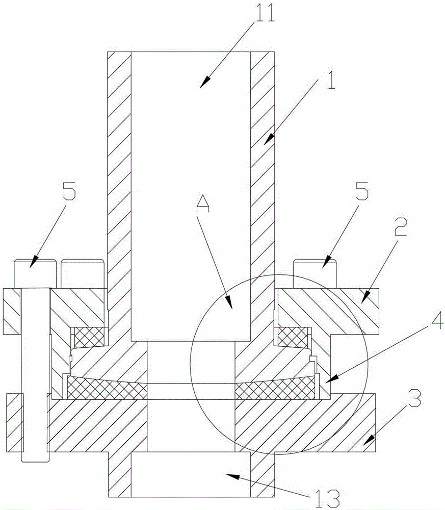
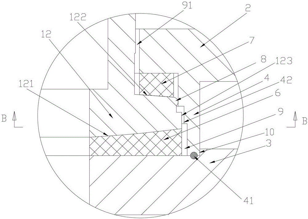
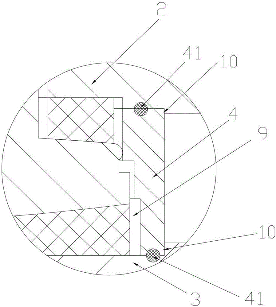
[0022] Such as figure 1 and figure 2 As shown, the spherical compensator used for pipeline connection includes a front pipeline 1 and a rear flange 3 which communicate internally, and the front channel 11 of the front pipeline 1 communicates with the rear channel 13 in the rear flange 3 . A spherical sealing ring 6 is arranged between the connecting end faces of the front pipe 1 and the rear flange 3 . The front pipe 1 is provided with a flange 12 whose outer diameter is larger than that of the front pipe 1 , and the connecting end surface of the front pipe 1 is arranged on the front end surface 121 of the flange. And the flange front end surface 121 is designed as a spherical surface matching the shape of the spherical sealing ring 6 to ensure that the front pipe 1 is in the axial swing mode, and the sealing between the flange front end surface 121 and the spheri...


PUM


Abstract

The invention discloses a pipeline compensating device, and particularly relates to a spherical compensator for pipe connection. The spherical compensator is convenient to install and low in height and comprises front pipelines and rear flanges, wherein interiors of the front pipelines are communicated with interiors of the rear flanges, a spherical seal ring is arranged on a connecting end face between the front pipelines and the rear flanges, a flange is arranged on the front pipeline, and the connecting end face is arranged at the front end of the flange; front flanges are arranged outside the front pipelines, and a front seal ring is installed between the front flanges and the rear end of the flange; a spherical seal ring is installed between the rear flanges and the rear end of the flange; the front flanges are connected with the rear flanges through fastening pieces. The spherical compensator reduces the height of the compensator, and is especially suitable for being used in working environments compact in position and small in installation space, simple in structure and convenient to install.

Description

technical field [0001] The invention relates to a pipeline compensator, in particular to a spherical compensator. Background technique [0002] Spherical compensators are often used in thermal pipelines, vaporization cooling devices of metallurgical equipment, and building pipelines. They mainly form a force couple through the rotation and bending of the ball head and the force arm, so that a pair of equal and opposite forces surround the central axis. Rotate to realize the absorption of pipeline expansion on both sides of the couple. [0003] Patent No. 201120559664.3 "A Spherical Compensator" discloses a spherical compensator that installs a sealing ring on the radially outer side of the sphere. Due to the small contact area of ​​the sealing ring, the load per unit area of ​​the sealing ring is relatively large. Easily damaged, causing leakage. [0004] Patent No. 200820300623.X "Rotary Joint" also discloses a structure of a spherical compensator, which uses an axial sph...

Claims


Application Information

Patent Timeline
Patent Type & Authority Patents(China)
IPC IPC(8): F16L51/00F16K27/12
Inventor 谢晓林谢家琪
Owner SICE ELECTRIC POWER EQUIP
Why Eureka
Try Eureka