
Plating method

A technology for plating parts and power supplies, which is applied in the direction of electrolysis, electrolysis components, cells, etc. It can solve the problems of affecting the quality of electroplating and uneven thickness of the plating layer, and achieve the effect of improving practicability, improving the quality of electroplating, and wide application range

Active Publication Date: 2016-05-04
东莞市五株电子科技有限公司
View PDF8 Cites 0 Cited by
  • Summary
  • Abstract
  • Description
  • Claims
  • Application Information

AI Technical Summary

Problems solved by technology

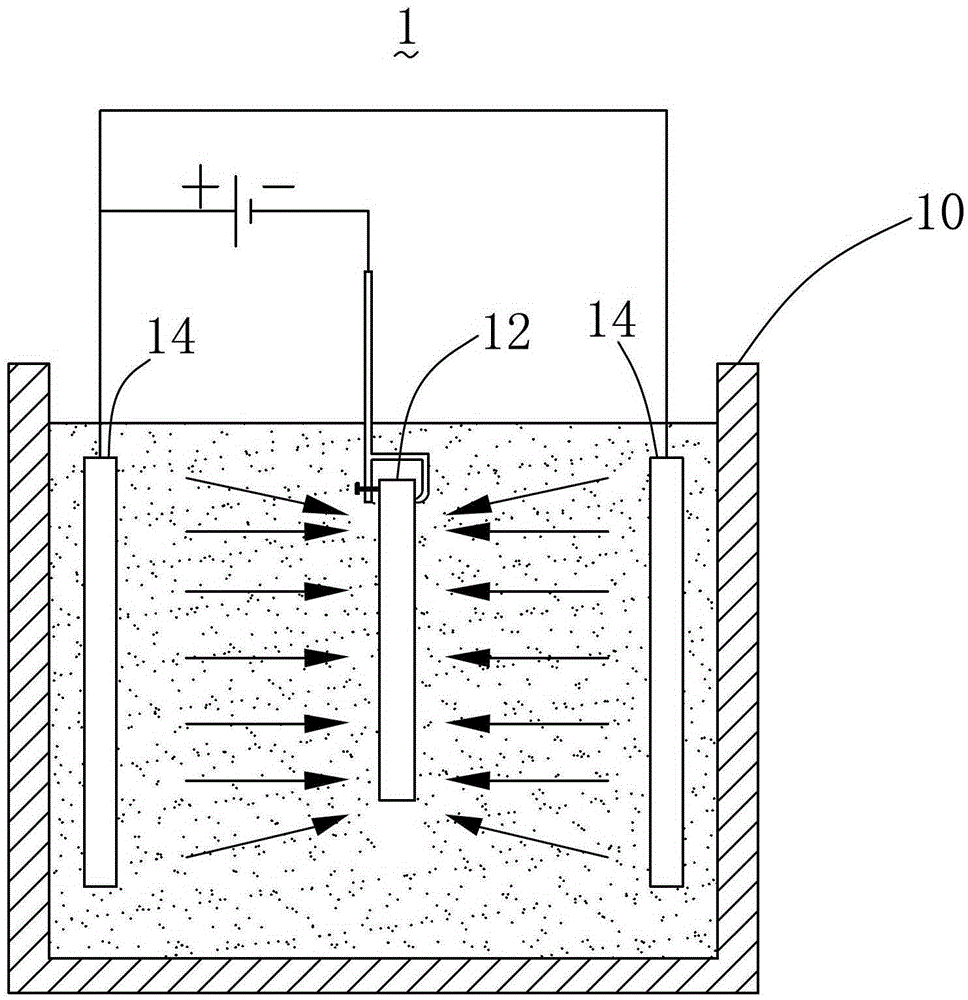
[0003] In the electroplating method of the prior art, because the area of ​​described plated piece 12 can be less than the area of ​​described anode 14 sometimes, therefore may cause the plating layer thickness of each part up and down of described plated piece 12 to be uneven, especially in described The thickness of the coating at the upper and lower ends of the plated piece 12 is inconsistent with the thickness of the coating at the middle position, which affects the quality of the plating

Method used


Image

  • Plating method
  • Plating method
  • Plating method

Examples


Embodiment Construction

[0025] The following will clearly and completely describe the technical solutions in the embodiments of the present invention with reference to the accompanying drawings in the embodiments of the present invention. Obviously, the described embodiments are only some, not all, embodiments of the present invention. Based on the embodiments of the present invention, all other embodiments obtained by persons of ordinary skill in the art without making creative efforts belong to the protection scope of the present invention.

[0026] The embodiment of the invention discloses an electroplating method, comprising:

[0027] Put a pair of anodes and the plated piece into the electroplating tank filled with electroplating solution, the pair of anodes are respectively arranged on the left and right sides of the plated piece and are respectively electrically connected to the positive pole of the power supply, and the plated piece and the power supply The negative pole of is electrically co...


PUM


Abstract

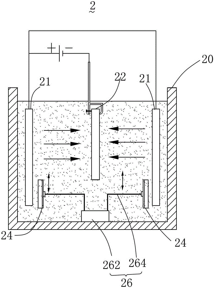
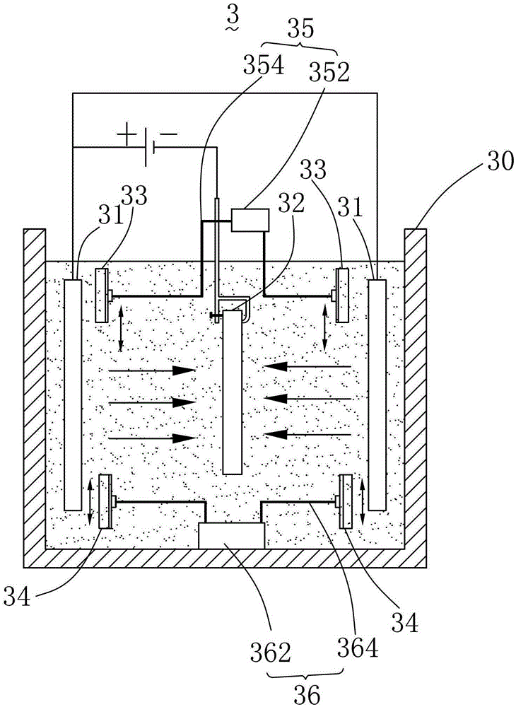
The invention provides an electroplating method, which comprises the following steps: a pair of anodes and an electroplated part are placed in a plating bath with a plating solution, the pair of anodes are respectively arranged at the left side and the right side of the electroplated part and enable electrically connected to the anode of the power supply respectively, the electroplated part enables electrically connected to the cathode of power supply for being as the cathode; a pair of first baffle plates are arranged between the pair of anodes and closed to one end of the electroplated part; according to the requirements of an electroplate area of the electroplated part, the first baffle plates are controlled to cover a part of area of the electroplated part; power supply is switched on, and the electroplated part is electroplated. The electroplating method is characterized in that the first baffle plates are arranged between the pair of anodes, the area of the electroplated part directly opposite to the anode can be adjusted in a flexible way, thereby uniform electroplating of part of the electroplated part can be selectively completed, and the uniform electroplating of the integral electroplated part can be completed, the electroplate quality is enhanced, the application scope is wide, and the practicality is obviously increased.

Description

technical field [0001] The invention relates to an electroplating method capable of controlling the electroplating area of ​​a plated piece. Background technique [0002] see figure 1 , a prior art electroplating equipment 1 includes an electroplating tank 10 , a plated piece 12 and a pair of anodes 14 . The electroplating tank 10 is filled with electroplating solution, the pair of anodes 14 are respectively electrically connected to the positive pole of the power supply, and the plating piece 12 is electrically connected to the negative pole of the power supply and serves as a cathode during the electroplating process. After the power is turned on, in the electroplating method of utilizing the electroplating equipment 1 to electroplate the plated piece 12, the metal cations in the electroplating solution are attracted by the negative charge on the surface of the plated piece 12, so that the metal cations on the surface of the plated piece 12 The surface gradually forms a ...

Claims


Application Information

Patent Timeline
Patent Type & Authority Patents(China)
IPC IPC(8): C25D5/02C25D21/12
Inventor 冉彦祥
Owner 东莞市五株电子科技有限公司
Learn More