Sliding block mechanism of louver and sliding block system with gear clutch turnover mechanism

A technology of gear clutch and turning mechanism, which is applied in the field of slider system and can solve problems such as unpublished transmission mechanism

Active Publication Date: 2012-12-26
HANGZHOU WOKASOLAR TECH
View PDF7 Cites 11 Cited by
  • Summary
  • Abstract
  • Description
  • Claims
  • Application Information

AI Technical Summary

Problems solved by technology

However, this invention patent application only discloses the combined structure of the combined louver and the sunshade and light guide

Method used


Image

  • Sliding block mechanism of louver and sliding block system with gear clutch turnover mechanism
  • Sliding block mechanism of louver and sliding block system with gear clutch turnover mechanism
  • Sliding block mechanism of louver and sliding block system with gear clutch turnover mechanism

Examples


Embodiment Construction

[0051] Attached below Figure 1-3 1 and the specific embodiment The present invention is described in further detail:

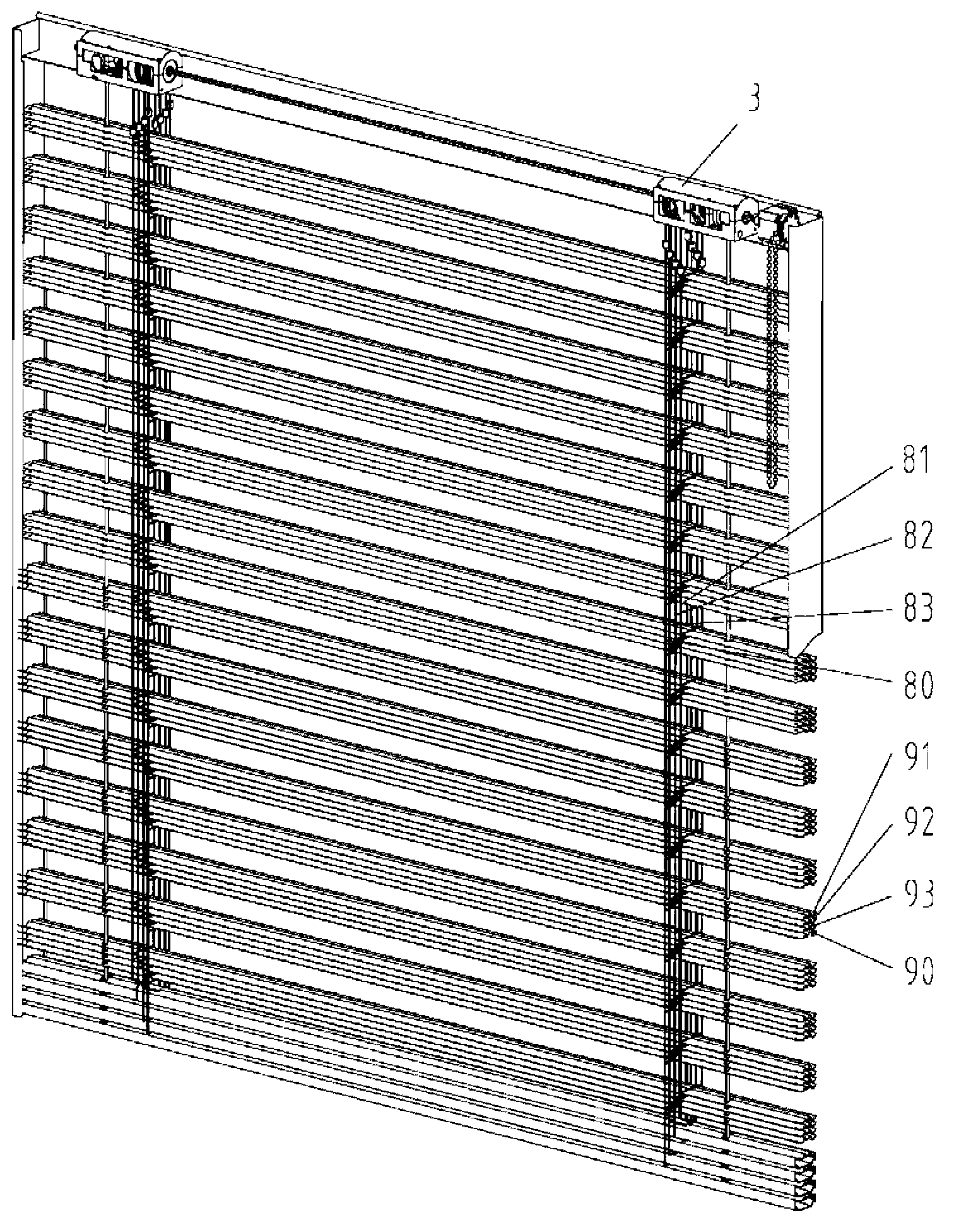
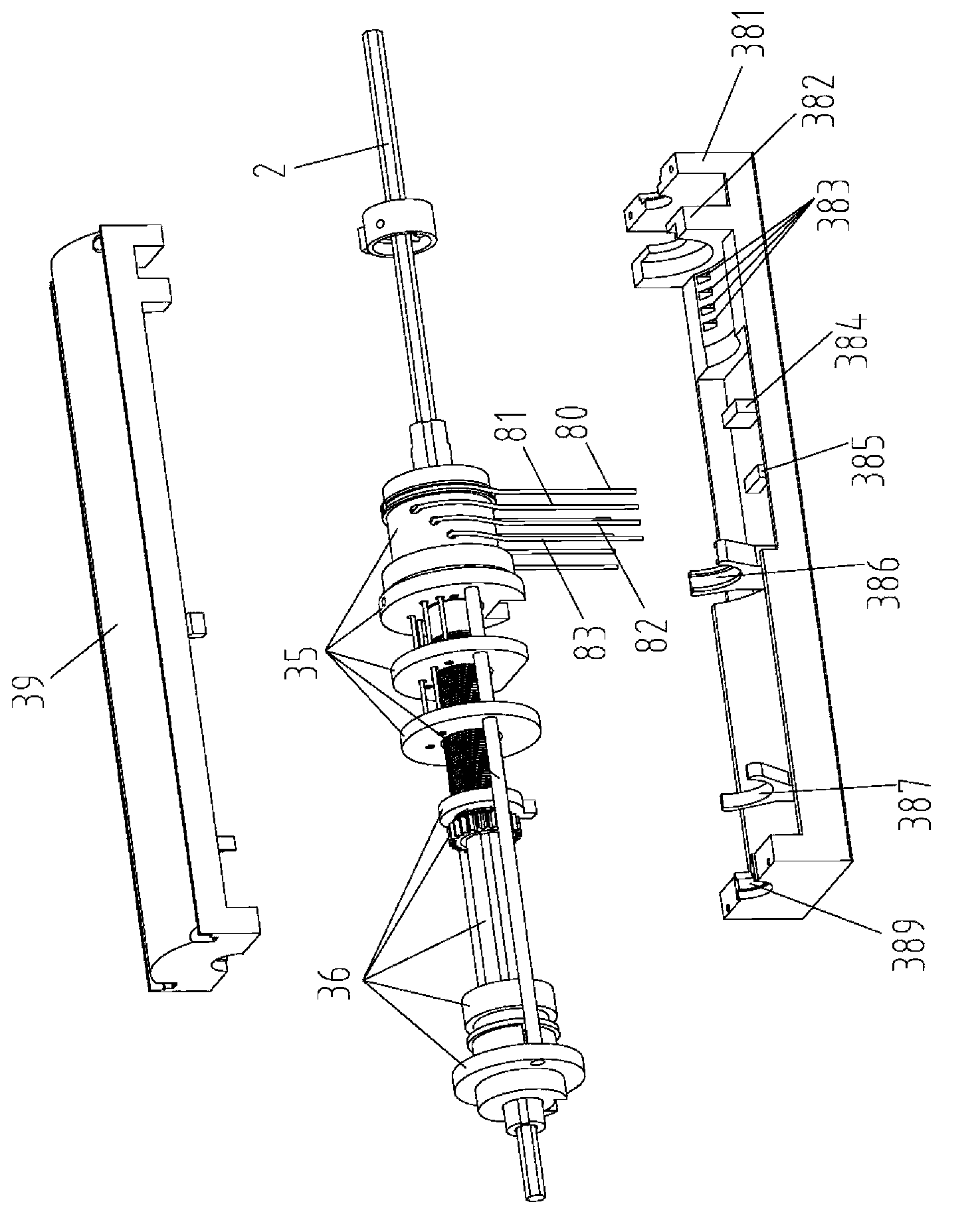
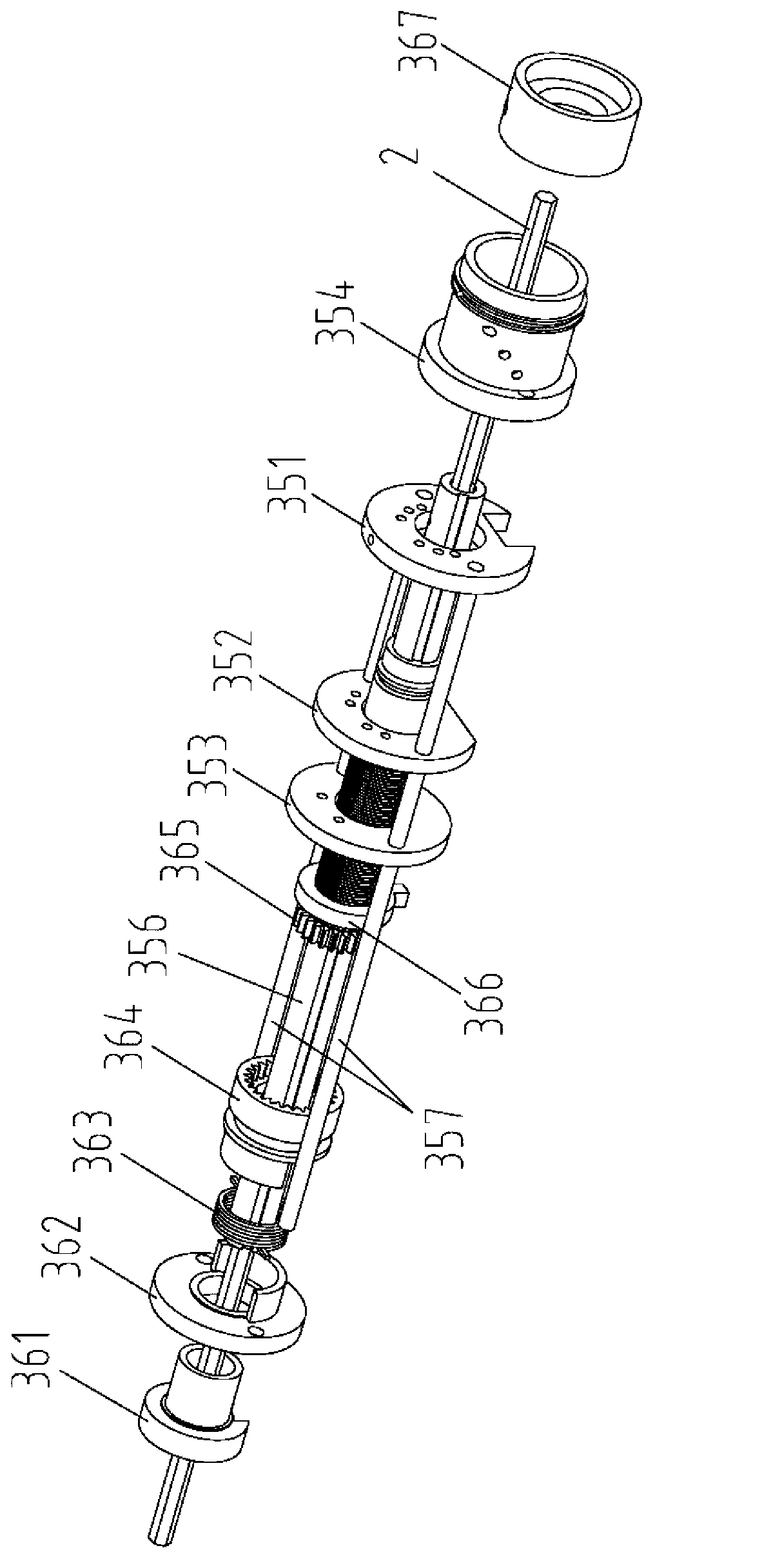
[0052] According to attached figure 2 with 3 The slider system for blinds includes a slider mechanism 35 and a gear clutch turning mechanism 36, the slider mechanism 35 and the gear clutch turning mechanism 36 are axially installed on the square shaft shaft 2, and the gear clutch turning mechanism 36 includes a fixed sleeve 361 1. The fixed sleeve 361 is connected with the flip disc 362, the flip disc 362 is embedded with a torsion spring 363, the flip disc 362 is connected with the torsion spring unlocking gear 364, the torsion spring unlocking gear 364 is connected with the clutch gear 365, and the hollow screw of the clutch gear 365 3651 passes through the fixed nut 366; the slider mechanism 35 includes the second slide block 351, the second slide block 352, the third slide block 353 and the turning cylinder 354, and the slide bar 357 passes through the...


PUM


Abstract

The invention relates to an accessory of a louver, in particular to a sliding block mechanism of the louver and a sliding block system composed of the sliding block mechanism and a gear clutch turnover mechanism. The sliding block mechanism of the louver comprises an overturning barrel, a sliding block is mounted on a lateral side of the overturning barrel, a sliding rod penetrates through the overturning barrel, the sliding block and a through hole in an overturning disk, the sliding block is axially mounted on a hollow screw rod of a clutch gear, and a limiting sleeve is mounted on the other side of the overturning barrel. The sliding block system composed of the sliding block mechanism and the gear clutch turnover mechanism comprises a base seat and a top cover. The sliding block mechanism and the gear clutch turnover mechanism are arranged on the base seat, a ladder-shaped belt is wound on the sliding block mechanism, and the sliding block mechanism and the gear clutch turnover mechanism are mounted on a square shaft along the axial direction.

Description

technical field [0001] The invention relates to a shutter accessory, in particular to a shutter mechanism and a slider system composed of the slider mechanism and a gear clutch overturning mechanism. Background technique [0002] The traditional blinds are composed of louver blades with an arc-shaped cross section, lift ropes, ladder belts, top rails and bottom rails. A rotary drive with self-locking function, a rotating shaft, and several winding lifts are installed in the top rail. The rope and the reel of the ladder belt are controlled. The rotating shaft passes through the rotary driver and the reel. A ladder belt is arranged between the top rail and the bottom rail. The lower end of the ladder belt is fixedly connected with the bottom rail. On the reel, a plurality of louvers arranged in parallel are worn in the horizontal cable of the ladder belt. A perforation is set at the symmetrical center of the cross section of the louver to allow the lifting rope to pass through...

Claims


Application Information

Patent Timeline
IPC IPC(8): E06B9/322E06B9/303
Inventor 张一飞武成尚
Owner HANGZHOU WOKASOLAR TECH
Why Eureka
Try Eureka