
Recognition method and device for micro-scale damage point in damage threshold measurement

A micro-scale, damage threshold technology, used in optical testing flaws/defects, etc., can solve problems such as wrong judgment results, limited recognition accuracy, and inability to provide damage points to achieve effective recognition.

Active Publication Date: 2012-12-26
TONGJI UNIV
View PDF5 Cites 9 Cited by
  • Summary
  • Abstract
  • Description
  • Claims
  • Application Information

AI Technical Summary

Problems solved by technology

First of all, during the measurement process, both the sample and the microscope have slight vibrations, especially when they have just moved to a new position, which will cause micron-scale shifts in the images taken at the same position at different times. If the two images are directly subtracted, the central coordinates of the image strong area do not directly correspond, which may easily lead to wrong judgment results; in addition, for a pulsed Nd:YAG laser with a working frequency of 10 Hz, the image exposure, acquisition, processing and The judgment time needs to be completed within 0.1s, so the exposure time is generally less than 10ms. In such a short period of time, due to the influence of the shooting environment such as the stability of the light source, the gray value of the image taken at the same position at different times has fluctuations. This affects the result of the subtraction of the two images; finally, this method can only simply determine whether the sample is damaged, and cannot provide more information about the damaged point, including position coordinates, original size and damaged size, etc.
Due to the above-mentioned reasons and deficiencies, the measurement error is increased, which limits the recognition accuracy of the two methods in damage threshold measurement for micron-scale damage points

Method used


Image

  • Recognition method and device for micro-scale damage point in damage threshold measurement
  • Recognition method and device for micro-scale damage point in damage threshold measurement
  • Recognition method and device for micro-scale damage point in damage threshold measurement

Examples


Embodiment

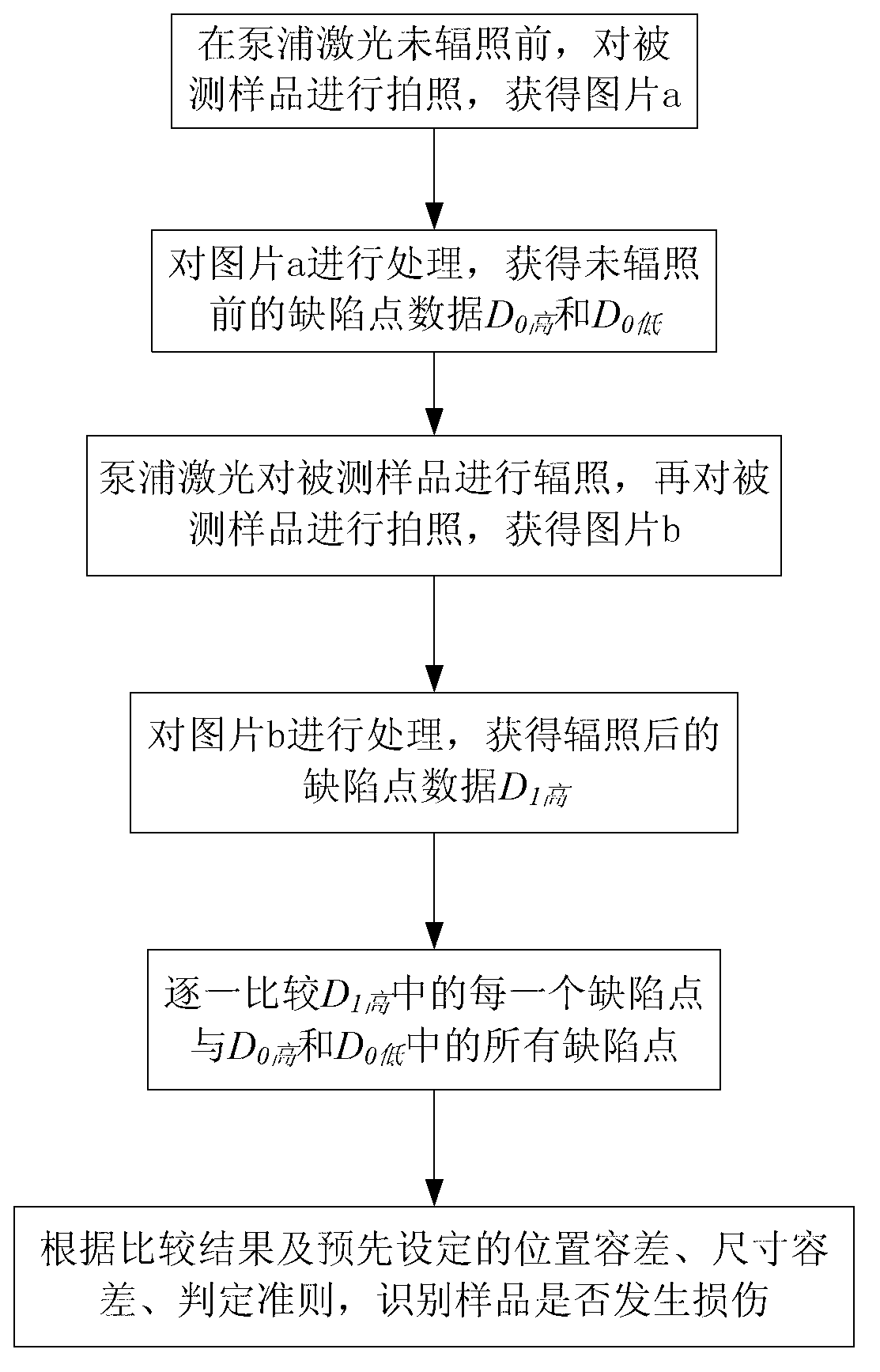
[0040] Such as figure 1 As shown, a method for identifying micro-scale damage points in damage threshold measurement, the method includes the following steps:

[0041] ① Fix the sample to be tested on the electric translation stage, use dark field illumination, align the online microscope to the position where the pump laser is irradiating the sample to be tested, and take pictures of the sample to be tested before the pump laser is irradiated, and obtain picture a, as shown in As shown in Figure 2(a), and send picture a to the computer.

[0042] ②The computer processes the picture a, according to the preset threshold T 高 and T 低 , respectively identify all gray levels in image a higher than T 高 and T 低 defect point, get the defect point data D 0高 and D 0低 .

[0043] ③The computer controls the pump laser to irradiate the tested sample, and the online microscope takes pictures of the irradiated tested sample to obtain picture b, as shown in Figure 2(b), and transmits it ...


PUM


Abstract

The invention relates to a recognition method and device for a micro-scale damage point in damage threshold measurement. The recognition method comprises the following steps of: photographing a tested sample by an on-line microscope before radiation of a pumping laser to obtain a picture a by using dark field illumination; processing the picture a by a computer, and recognizing all defect points of which the gray levels are higher than thresholds T high and T low in the picture a to obtain deflect point data D0 high and D0 low respectively; photographing the tested sample after radiation by the on-line microscope to obtain a picture b, and recognizing all defect points of which the gray levels are higher than the T high in the picture b by the computer to obtain defect point data D1 high; comparing each defect point in the D1 high with all defect points in D0 high and D0 low one by one; and recognizing whether the sample is damaged according to the comparison result and a judgment rule by the computer,. The recognition device comprises the pumping laser, an electric translation table, a lighting source, the on-line microscope and the computer. Compared with the prior art, the recognition method and the recognition device have the advantages of capability of effectively recognizing the micro-scale damage points, high recognition accuracy and the like.

Description

technical field [0001] The invention relates to a method and device in the field of testing the anti-laser damage performance of optical components, in particular to a method and device for identifying micro-scale damage points in damage threshold measurement. Background technique [0002] Laser thin films are key components in high-power laser systems, and the laser damage threshold of thin films is one of the important bottlenecks that limit the development of high-power laser technology in the direction of high power and high energy. In order to deeply analyze the damage performance and damage mechanism of laser thin films, and accurately evaluate the laser damage resistance of optical components, it is necessary to continuously develop and improve the measurement technology of laser damage threshold, improve the measurement precision and accuracy of damage threshold, and guide the thin film preparation process. optimization and improvement. Due to the complexity of the ...

Claims


Application Information

Patent Timeline
Patent Type & Authority Applications(China)
IPC IPC(8): G01N21/88
Inventor 马彬张艳云马宏平程鑫彬焦宏飞王占山
Owner TONGJI UNIV
Learn More