System powered phase comparison device

A technology of phase comparison and equipment, applied in the field of comparators, can solve problems such as heavy solution

Active Publication Date: 2017-06-09
SCHNEIDER ELECTRIC IND SAS
View PDF3 Cites 0 Cited by
  • Summary
  • Abstract
  • Description
  • Claims
  • Application Information

AI Technical Summary

Problems solved by technology

But the solution is still heavy

Method used


Image

  • System powered phase comparison device
  • System powered phase comparison device
  • System powered phase comparison device

Examples


Embodiment Construction

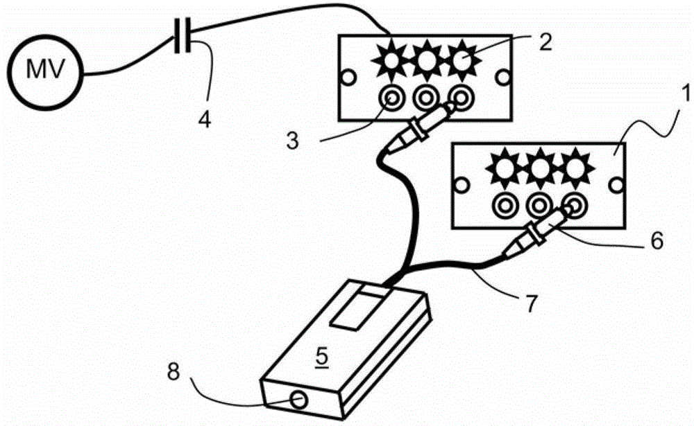
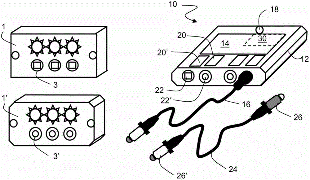
[0022] The comparator 10 according to the invention enables connection via the front panel of the VPIS1 in place of an output 3 indicating the presence of voltage on each phase of the two medium voltage equipment units. In the usual manner, the phase comparison device 10 comprises a housing 12 comprising electronic comparison means 14 (preferably printed circuit cards) which receive, via rectification means 16, signals representing the phases of the two origins, And if a difference (for example a difference of more than 30°) is observed between the two input signals, a signal corresponding to the triggering of the alarm means 18 is given as a result.

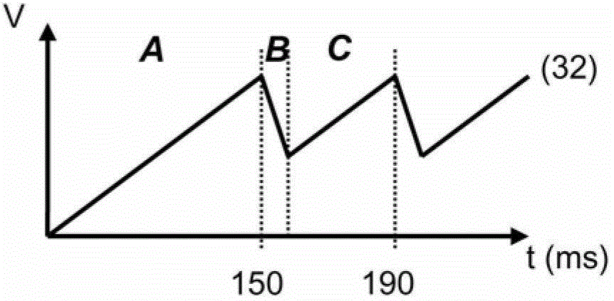
[0023] The comparison means 14 according to the invention can use different existing systems, and comparison devices with tri-state and with JK flip-flops, Gilbert multipliers or XOR gates can be taken care of by the solution according to the invention. When two signals representing phases corresponding to voltages exhibiting an...


PUM


Abstract

In order to check the phase match between two medium voltage equipped units equipped with VPIS (1, 1'), a phase comparator (10) can be used. The connector (16) of the comparator (10) is plugged into the terminals (3, 3') of the two VPIS (1, 1') in order to obtain a signal representing the voltage flowing therein, and the part (14) compares the signal to The LED (18) is illuminated where a mismatch is observed. According to the invention, the connector (16) of the comparator (10) is suitable for comparators (10) that can be used for two VPIS (1, 1') of different generations, such as With different connection terminals (3, 3'). The comparator (10) is powered directly by means of the available voltage signal of the VPIS (1, 1'), and the power supply management part (30) of the diode (18) has been developed in order to meet the safety conditions when the diode (18) is illuminated, while Regardless of the small amount of energy available.

Description

technical field [0001] The invention relates to a comparator for checking phase matching, especially between two medium voltage equipment units, for power systems ranging for example from 3 to 40 kV and 50 Hz or 60 Hz. More specifically, the invention relates to an optimal management of the energy of the phase indicators to minimize their consumption, and / or to the optimal management of the phase comparators to further enable the system power supply via their connected voltage indicating devices. The invention also relates to the connector of the comparator to enable a simpler use in cases where the voltage indicators do not have the same output characteristics. Background technique [0002] In medium-voltage (MV) installations, in order to check whether the system lacks voltage or is in a live state, a voltage detector that complies with IEC standard 61243 is equipped. In order to provide information about the voltage status of the main circuit of the equipped unit, these ...

Claims


Application Information

Patent Timeline
Patent Type & Authority Patents(China)
IPC IPC(8): G01R25/00
CPCG01R1/04G01R19/155G01R25/00
Inventor P.考斯C.莫利尔F.博多纳多
Owner SCHNEIDER ELECTRIC IND SAS
Why Eureka
Try Eureka