Power transmission line self-power collecting device

A technology of transmission lines and self-collection of electricity, which is applied in the field of power transmission to meet the requirements of electricity consumption and prolong the service life

Inactive Publication Date: 2012-12-26
上海大乘电气科技有限公司
View PDF3 Cites 7 Cited by
  • Summary
  • Abstract
  • Description
  • Claims
  • Application Information

AI Technical Summary

Problems solved by technology

[0005] In order to solve the above-mentioned problems existing in the prior art, the present invention provides a power transmission line self-power collection device, which avoids the problem of device damage or insufficient power caused by the induction power supply being too large or too small beyond the power threshold range

Method used


Image

  • Power transmission line self-power collecting device
  • Power transmission line self-power collecting device

Examples


Embodiment Construction

[0020] In view of the fact that the number of coil turns in the induction power-taking coil in the prior art is fixed, the operating power supply range is limited, the flexibility is poor, and it cannot be adaptively adjusted according to the actual situation, and problems such as insufficient power supply or overload damage to devices occur.

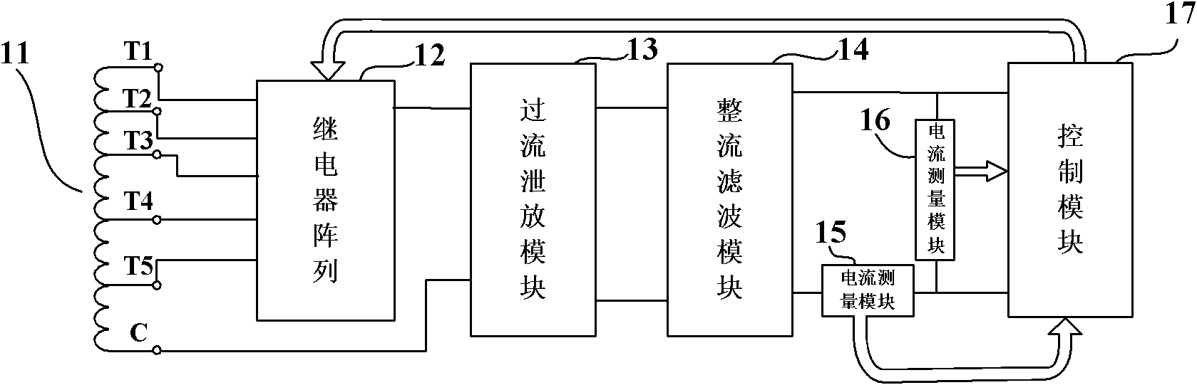
[0021] Therefore, the inventor of the present invention has improved the existing technology and proposed a new type of self-powering device for transmission lines, which has secondary windings with multiple taps corresponding to different coil turns, so that it can adapt itself according to the actual situation Switch taps to ensure a steady supply of power.

[0022] The self-powered device proposed by the present invention will be described in detail below through specific embodiments.

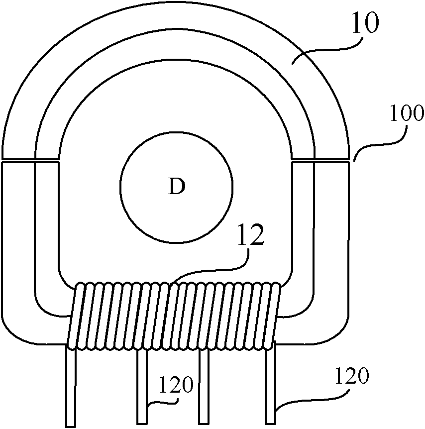
[0023] figure 1 A schematic structural view of the power-taking coil in the self-power-taking device of the present invention is shown. Such as fi...


PUM


Abstract

The invention provides a power transmission line self-power collecting device. The power transmission line self-power collecting device comprises a magnetic core, a secondary side winding with a plurality of taps corresponding to the numbers of windings of different coils, a relay array for switching the plurality of taps of the secondary side winding, a rectifying and filtering module for rectifying and filtering an alternating current power output via the secondary side winding and then outputting a direct current power, a current measuring module for measuring the current of the secondary side winding, a voltage measuring module for measuring the voltage of the secondary side winding, and a control module for controlling the relay array to switch the taps in the secondary side winding after the calculated power is determined beyond the range of a power threshold. Compared with the prior art, the self-power collecting device can switch the taps in a self-adaptive way when the power is beyond the scope of the power threshold, thus the power supply can be kept in the scope of the power threshold always, and moreover, the self-power supply device can be protected, so the service life can be prolonged; and the power can be continuously and stably supplied to the follow-up electric equipment, and the requirements of the electric equipment on power can be met.

Description

technical field [0001] The invention relates to the field of electric power transmission, in particular to a self-feeding device applied to a high-voltage transmission line. Background technique [0002] A large number of pole-mounted switchgear, line monitoring equipment, control equipment, etc. need to be installed on the high-voltage transmission line to ensure the normal and safe operation of the high-voltage transmission line. However, there are relatively few types of electrical equipment installed near high-voltage transmission lines and at the same potential as high-voltage transmission lines. The main reason is that the high-voltage insulation problem cannot be solved simply and efficiently, making it difficult for these equipment to be directly powered by the ground. [0003] With the development of technology, there are more and more equipment working on high-voltage transmission lines, such as line inspection robots, live working robots, online monitoring equipme...

Claims


Application Information

Patent Timeline
Patent Type & Authority Applications(China)
IPC IPC(8): H02J17/00H02H3/42H02H9/02H02J50/10
Inventor 曾奕王盛贵曾品卓
Owner 上海大乘电气科技有限公司
Why Eureka
Try Eureka