Loudspeaker apparatus with circumferential, funnel-like sound outlet opening

A technology of loudspeaker and output port, which can be used in sound-producing instruments, frequency/directional characteristic devices, instruments, etc., and can solve problems such as being too high and unusable.

Active Publication Date: 2012-12-26
弗兰克·赫尔德
View PDF6 Cites 22 Cited by
  • Summary
  • Abstract
  • Description
  • Claims
  • Application Information

AI Technical Summary

Problems solved by technology

Similarly, in the special field, within the acceptable structure size, the narrow bandwidth, especially the excessively high lower cut-off frequency, cannot be used

Method used


Image

  • Loudspeaker apparatus with circumferential, funnel-like sound outlet opening
  • Loudspeaker apparatus with circumferential, funnel-like sound outlet opening
  • Loudspeaker apparatus with circumferential, funnel-like sound outlet opening

Examples


Embodiment Construction

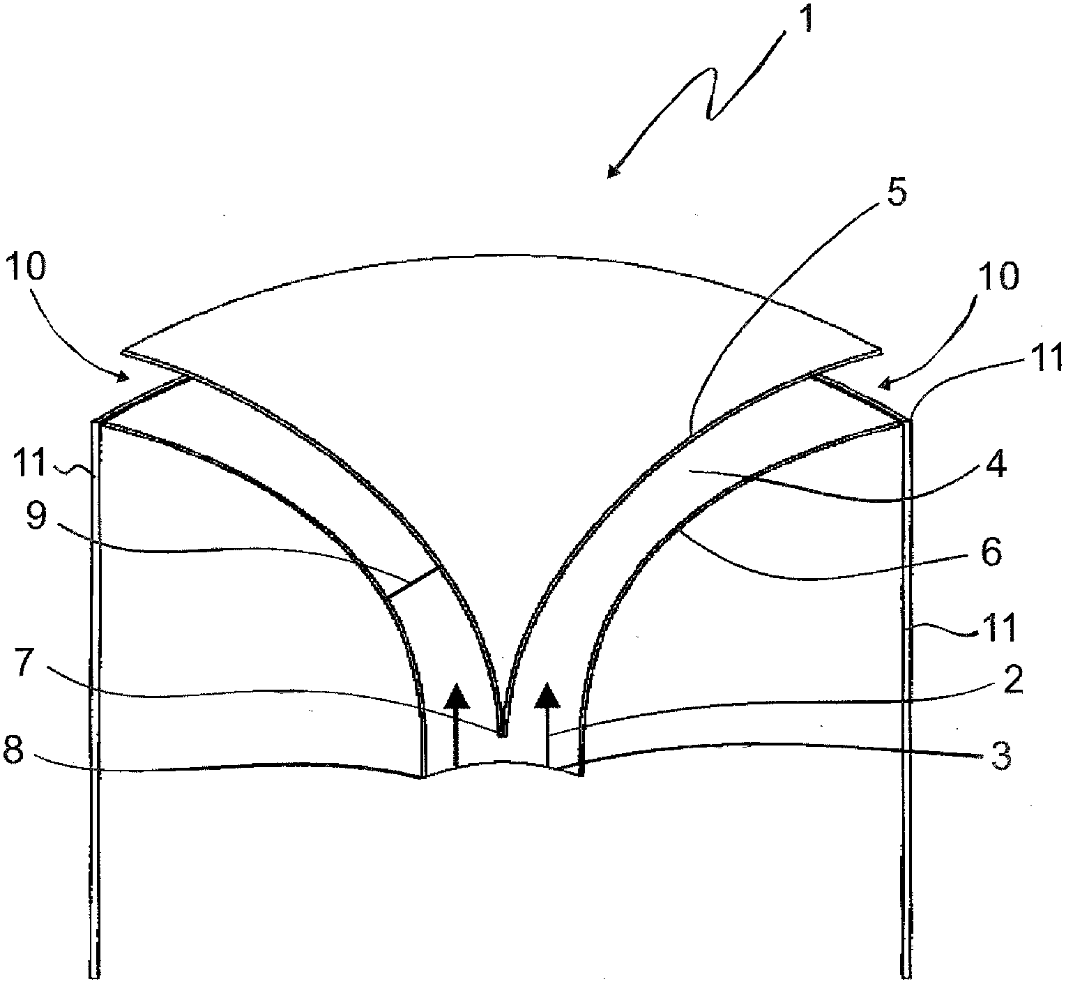
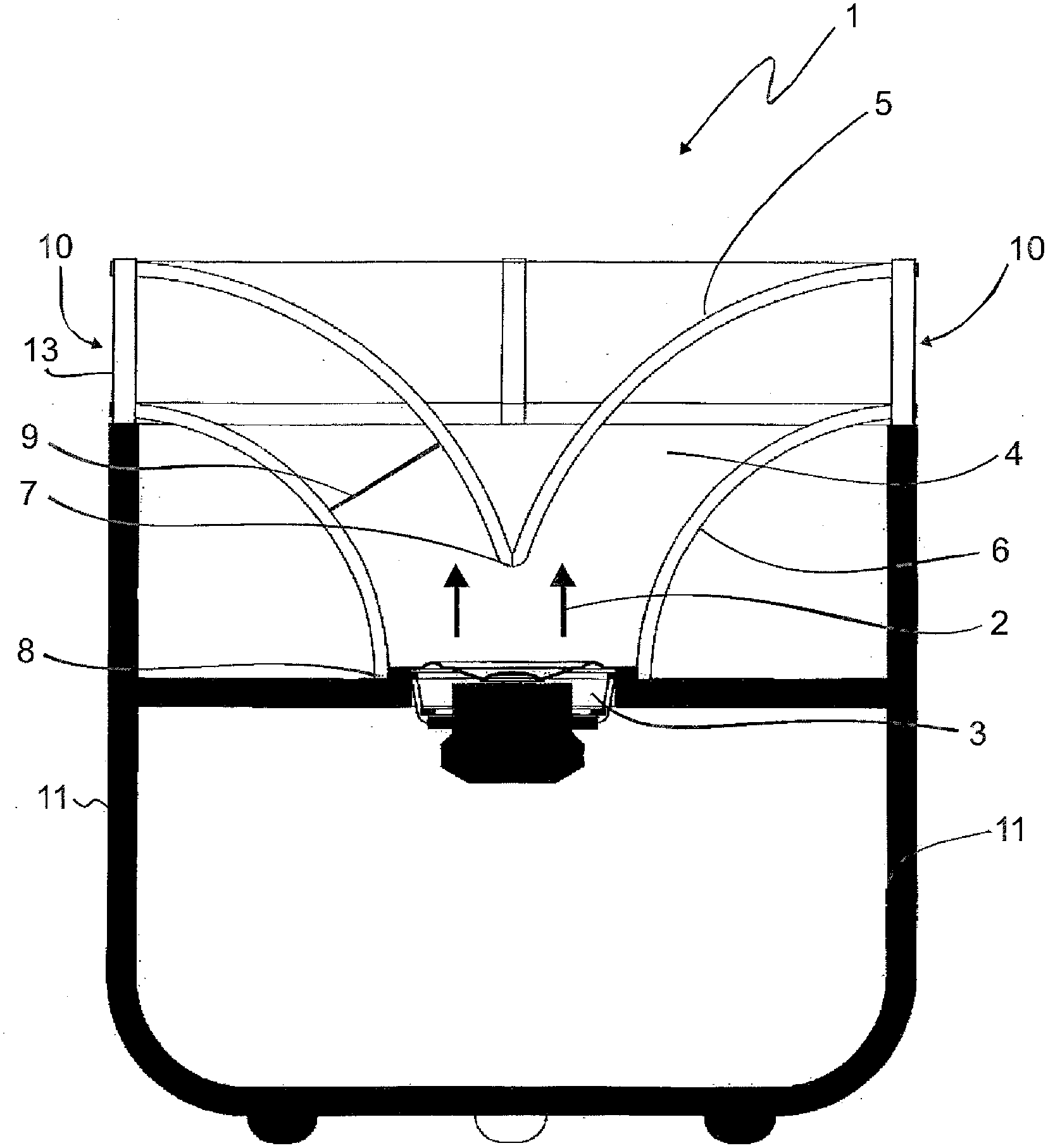
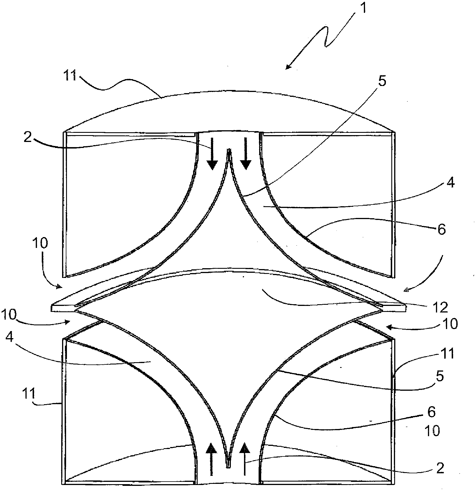
[0052] figure 1 It is a side view of the speaker device 1 . In this embodiment, at least one sound wave conduction channel 4 is arranged on the sound wave radiation direction 2 of the sound wave generating member 3, and the sound wave conduction channel 4 is designed as a boundary 5 arranged radially on the inside and a boundary 6 arranged radially on the outside. the intermediate space between. In this embodiment, the boundary 5 and the boundary 6 are designed to be funnel-shaped. The protrusion is equivalent to 1 / 4 circumference or 1 / 4 ellipse circumference. The border 5 arranged radially on the inside terminates in a tip 7 at the point closest to the sound wave generating element 3 . The radially outer boundary 6 ends flush with the sound wave generator 3 in a region 8 , the region 8 being closest to the sound wave generator 3 .

[0053] The projections of the radially inner boundary 5 and the radially outer boundary 6 are selected such that the cross section 9 of the s...


PUM


Abstract

The invention relates to a loudspeaker apparatus which comprises at least one sound generation means, wherein an at least partially sound-conducting channel is arranged in a sound radiation direction of the sound generation means and is suitable for directing sound emerging from the sound generation means along the course of the sound-conducting channel such that the sound emerges from the loudspeaker apparatus at a second end of the sound-conducting channel, which end is in the form of a sound outlet opening, at a radiation angle which is defined by the sound outlet opening.

Description

technical field [0001] The invention relates to a loudspeaker device comprising at least one sound generation means and a channel for conducting sound waves at least locally, said channel being located in the direction of sound radiation of said sound generation means, said channel being adapted to follow the sound wave The course of the conduction channel guides the sound wave generated by the sound wave generating member, so that the sound wave at a certain radiation angle is generated at the second end of the sound wave conduction channel in the form of the sound wave output port of the speaker device, and the radiation angle is determined by The sound wave output port is determined. Background technique [0002] Loudspeaker devices that radiate the generated sound waves in all directions have already appeared in the prior art. In this case, the sound-reflecting medium, mainly the cone, is located in front of the sound-generating member, so that the radiated sound waves ...

Claims


Application Information

Patent Timeline
Patent Type & Authority Applications(China)
IPC IPC(8): H04R1/34G10K11/02
CPCH04R1/345H04R1/30G10K9/00
Inventor 弗兰克・赫尔德
Owner 弗兰克·赫尔德
Why Eureka
Try Eureka