
Anti-slipping supporting rail assembly

A technology for supporting rails and anti-falling off, which is applied to rack/frame structure, furniture parts, household appliances, etc., can solve the problem of not revealing anti-falling safety devices, etc.

Active Publication Date: 2013-01-02
KING SLIDE WORKS CO LTD +1
View PDF5 Cites 5 Cited by
  • Summary
  • Abstract
  • Description
  • Claims
  • Application Information

AI Technical Summary

Problems solved by technology

[0003] The aforementioned patents do not disclose that the rails of the slide rail assembly have a safety device to prevent falling off when they are fully extended

Method used


Image

  • Anti-slipping supporting rail assembly
  • Anti-slipping supporting rail assembly
  • Anti-slipping supporting rail assembly

Examples


Embodiment Construction

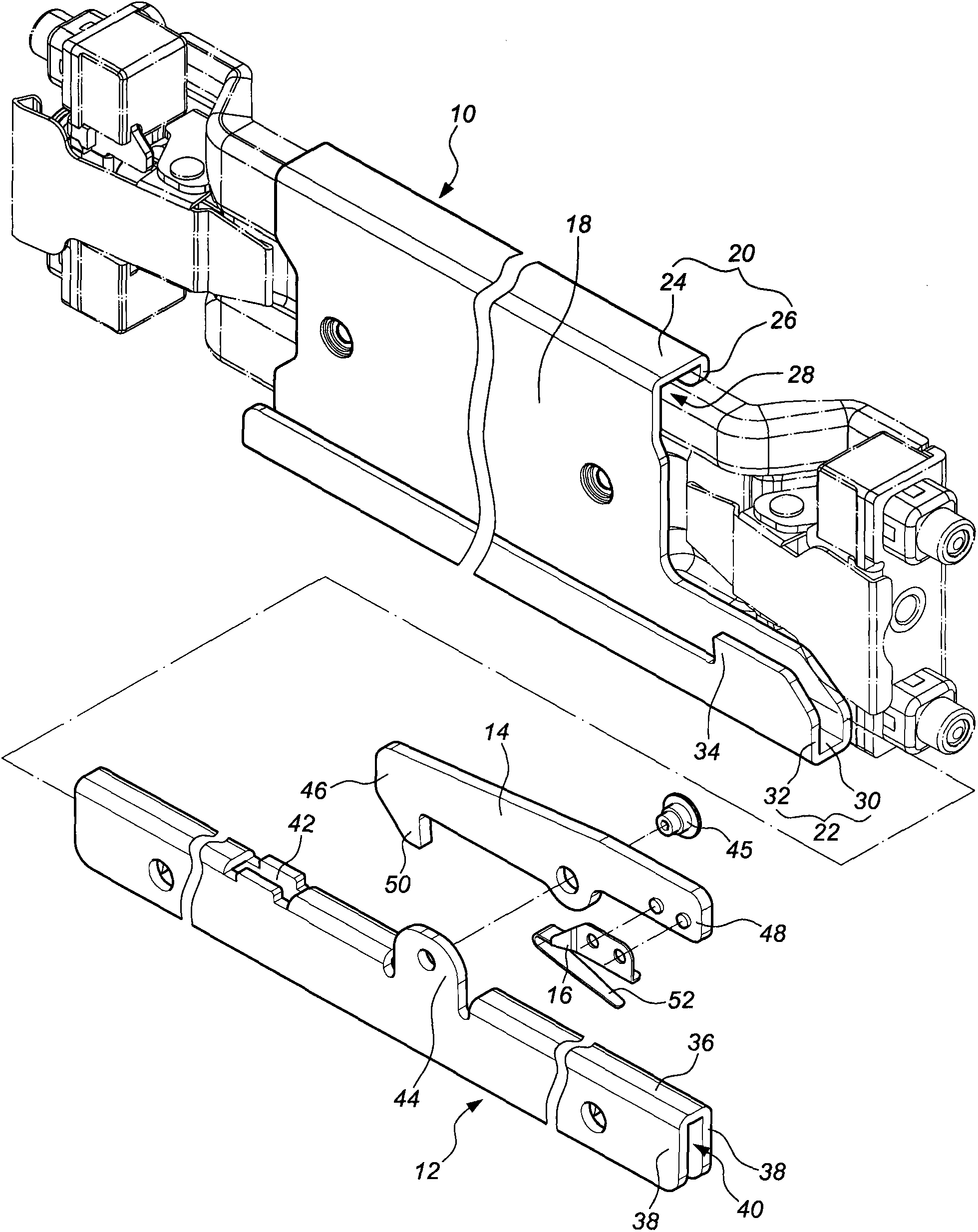
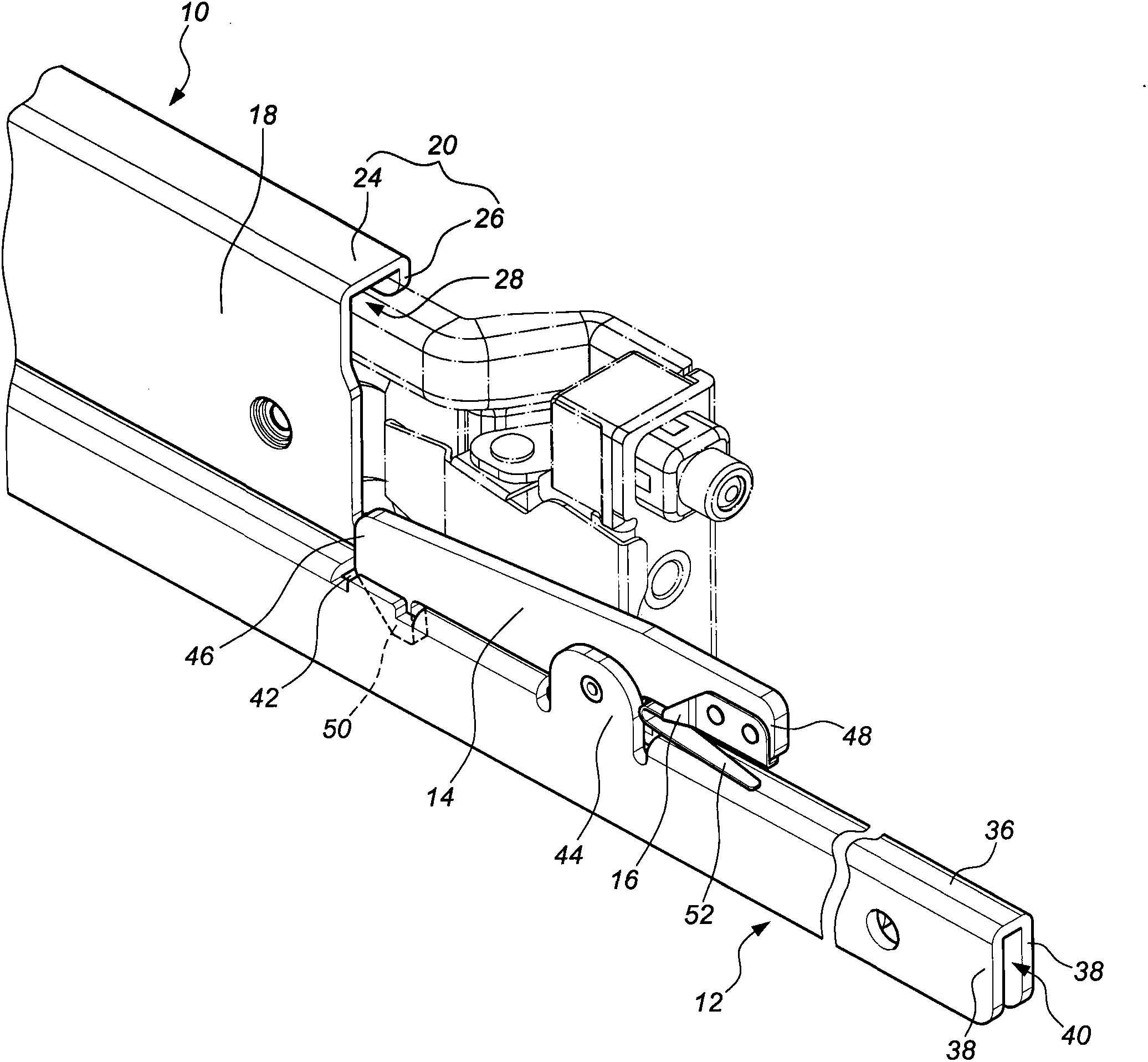
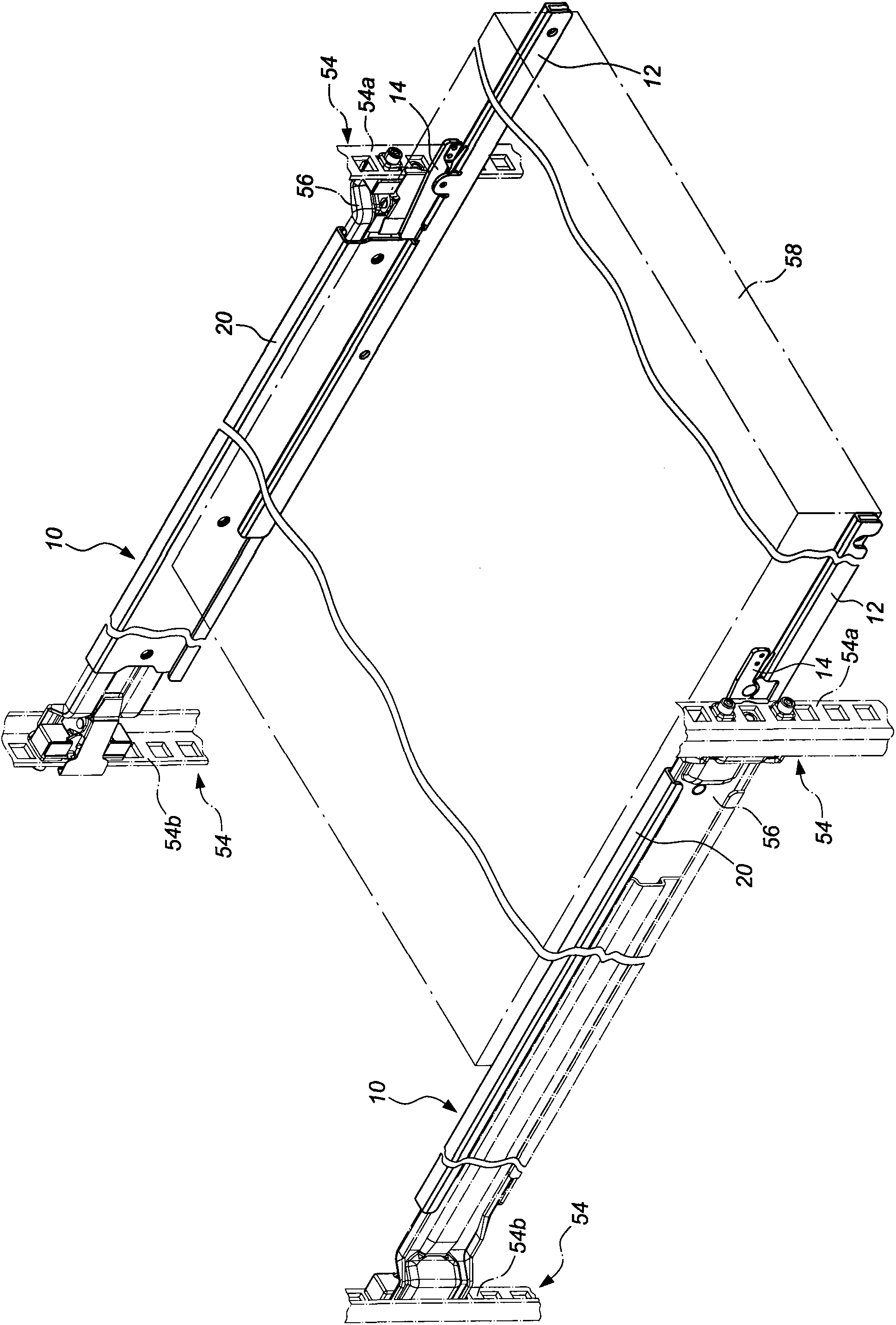
[0018] Such as figure 1 and figure 2 A supporting rail assembly showing a preferred embodiment of the present invention includes a first rail 10 , a second rail 12 , a locking member 14 and an elastic member 16 . in:

[0019] The first rail 10 includes a vertical board 18 , an upper rail body 20 and a lower rail body 22 ; the upper rail body 20 extends transversely from the top of the vertical board 18 toward a first direction and is bent downward. The lower rail body 22 extends transversely from the bottom end of the vertical plate 18 toward a second direction and is bent upward, and the second direction is opposite to the first direction. Wherein, the upper rail body 20 includes a first horizontal section 24 and a first vertical section 26 extending vertically downward from the end of the first horizontal section 24, the first vertical plate 18 and the first horizontal section 24 and the first vertical section 26 jointly form a first channel 28; the lower rail body 22 in...


PUM


Abstract

The invention relates to an anti-slipping supporting rail assembly which comprises a first rail, a second rail, a snapping piece and an elastic piece. The first rail comprises a blocking wall; the second rail is hung on the first rail for sliding and provided with a sliding groove; the snapping piece is connected with the second rail in a pivoting mode and provided with a first end and a second end, and the first end of the snapping piece is provided with a blocking portion; and the elastic piece is arranged between the second end of the snapping piece and the second rail to provide an elastic force for acting on the snapping piece, the blocking portion of the first end of the snapping piece extends into the sliding groove of the second rail by means of the elastic force of the elastic piece, the blocking portion longitudinally corresponds to the blocking wall of the first rail, and the second rail abuts against the blocking wall of the first rail by means of the blocking portion of the snapping piece to form a positioning blocking point when the second rail extends out to slide to a preset position relative to the first rail.

Description

technical field [0001] The invention relates to a support rail assembly, in particular to an anti-slip support rail assembly, which can prevent the rail parts of the support rail assembly from falling off when unfolded. Background technique [0002] U.S. Patent No. 6,547,081 "slide assembly for use in a rack assembly" invented by Kaminski, the abstract discloses a high-capacity, low-profile, low-friction slider assembly used in a rack assembly, in one embodiment wherein the invention comprises a first longitudinal member having a central portion, a first upwardly extending portion on one side and a second upwardly extending portion on the other side and a second longitudinal member having a central portion member, a first downwardly extending portion on one side and a second downwardly extending portion on the other side. The second longitudinal member is slidably coupled to the first longitudinal member such that the second longitudinal member can slide longitudinally agai...

Claims


Application Information

Patent Timeline
IPC IPC(8): A47B88/08H05K7/18A47B88/49
Inventor 陈庚金张维成王俊强
Owner KING SLIDE WORKS CO LTD
Learn More