This helps you quickly interpret patents by identifying the three key elements:
Problems solved by technology
Method used
Benefits of technology
Problems solved by technology
[0013] However, the method of making the acceleration and deceleration based on the lateral jerk is when the vehicle generates lateral motion, and the method of making the acceleration and deceleration associated with the lateral motion, such as deceleration before entering a curved road or on a straight line, does not occur on the vehicle. The deceleration in the state of lateral movement cannot be set
Method used
Image
Click on the blue label to locate the original text in one second.
Reading with bidirectional positioning of images and text.
Examples
no. 1 approach
[0135] Below, use Figure 16 ~ Figure 21 , the configuration and operation of the vehicle motion control device according to the first embodiment of the present invention will be described.
[0136] First, use Figure 16 , the configuration of the vehicle motion control device according to the first embodiment of the present invention will be described.
[0137] Figure 16 is a system block diagram showing the configuration of the vehicle motion control device according to the first embodiment of the present invention.
[0138]The vehicle motion control device 1 of the present embodiment is mounted on a vehicle, and includes: a curve shape obtaining mechanism 2 for obtaining the shape of a curve ahead of the vehicle; a vehicle position obtaining mechanism 3 for obtaining the position of the vehicle; The vehicle motion control calculation unit 4 calculates the front-rear acceleration generated by the vehicle with the information obtained by the vehicle position acquisition u...
no. 2 approach
[0210] Below, use Figure 22 to Figure 26 , the configuration and operation of the vehicle motion control device according to the second embodiment of the present invention will be described. In addition, the same code|symbol is attached|subjected to the same structure as 1st Embodiment, and the detailed description is abbreviate|omitted.
[0211] First, use Figure 22 , the structure of the vehicle motion control device according to the second embodiment of the present invention will be described.
[0212] Figure 22 is a system block diagram showing the configuration of a vehicle motion control device according to a second embodiment of the present invention.
[0213] The vehicle motion control device 1' of the second embodiment is mounted on a vehicle, and includes a curve shape acquiring mechanism 2 for acquiring the curve shape ahead of the vehicle, a vehicle position acquiring mechanism 3 for acquiring the position of the vehicle, a vehicle motion information acquirin...
no. 3 approach
[0296] Below, use Figure 27 and Figure 28 , the structure and operation of the vehicle motion control device according to the third embodiment of the present invention and its modification will be described. In addition, the same code|symbol is attached|subjected to the same structure as 1st, 2nd embodiment, and detailed description is abbreviate|omitted.
[0297] First, use Figure 27 , the configuration of the vehicle motion control device according to the third embodiment of the present invention will be described.
[0298] Figure 27 is a system block diagram showing the configuration of a vehicle motion control device according to a third embodiment of the present invention.
[0299] The vehicle motion control device 1" according to the third embodiment includes: a curve shape acquisition mechanism 2 for acquiring the curve shape ahead of the vehicle; a vehicle position acquisition mechanism 3 for acquiring the position of the vehicle; and a vehicle communication de...
PUM
Abstract
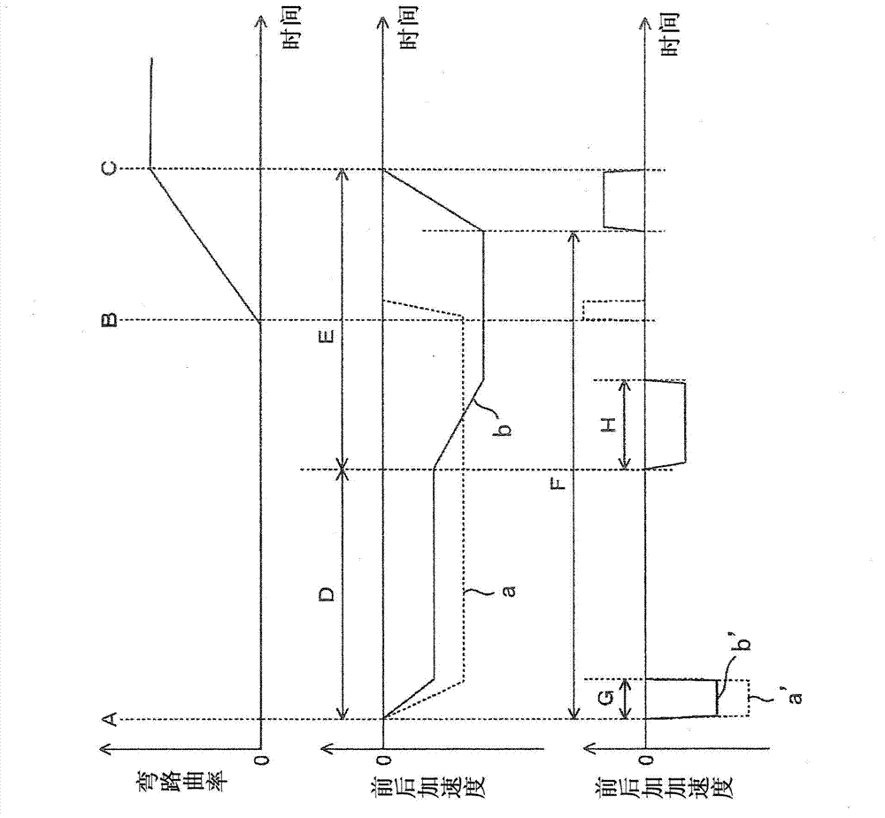
There is provided a vehicle motion controlsystem which carries out acceleration and deceleration of a vehicle which satisfies driving feeling of a driver even in the state where a lateral motion of the vehicle is not involved. The vehicle motion controlsystem includes a curve shape acquisition section 2 for acquiring a curve shape ahead of an own vehicle, an own vehicle position acquisition section 3 for acquiring a position of the own vehicle, and a vehicle motion control calculation section 4 for calculating a command value of a longitudinal acceleration generated for the vehicle based on the curve shape and the position of the own vehicle. The vehicle motion control calculation section 4 calculates a plurality of negative longitudinal acceleration command values during travel of the own vehicle from before a curve to a point where a curve curvature becomes constant or maximum after the vehicle enters into the curve. The longitudinal acceleration command values are changed based on at least one of: an estimate of the maximum lateral acceleration which is presumably generated during traveling a curve ahead of the own vehicle; a grade of the road ahead of the own vehicle, pedal operation by the driver, and a turning direction.
Description
technical field [0001] The present invention relates to a vehicle motion control device, and more particularly to a vehicle motion control device that accelerates and decelerates a vehicle in order to make the motion state of the vehicle appropriate. Background technique [0002] Conventionally, there is known a system that decelerates when the lateral acceleration generated by the vehicle exceeds a set value based on curved road information from a navigation system and lateral acceleration when turning (for example, Patent Document 1). [0003] In this device, in order to prevent the magnitude of the lateral acceleration generated when passing a curved road from becoming more than a set value, the target vehicle when traveling on a curved road is set based on a preset lateral acceleration set value and the curvature of the curved road ahead of the vehicle. Speed, based on the target vehicle speed and the actual vehicle speed, the necessary deceleration is made. This method...
Claims
Application Information
Patent Timeline
Application Date:The date an application was filed.
Publication Date:The date a patent or application was officially published.
First Publication Date:The earliest publication date of a patent with the same application number.
Issue Date:Publication date of the patent grant document.
PCT Entry Date:The Entry date of PCT National Phase.
Estimated Expiry Date:The statutory expiry date of a patent right according to the Patent Law, and it is the longest term of protection that the patent right can achieve without the termination of the patent right due to other reasons(Term extension factor has been taken into account ).
Invalid Date:Actual expiry date is based on effective date or publication date of legal transaction data of invalid patent.

