

Slip suppression control for a motorcycle with an on/off input device
a technology of input device and control system, which is applied in the direction of vehicle position/course/altitude control, braking system, instruments, etc., can solve problems such as degrading driving feel, and achieve the effect of improving driving feel
- Summary
- Abstract
- Description
- Claims
- Application Information
AI Technical Summary
Benefits of technology
Problems solved by technology
Method used
Image

Examples
embodiment 1
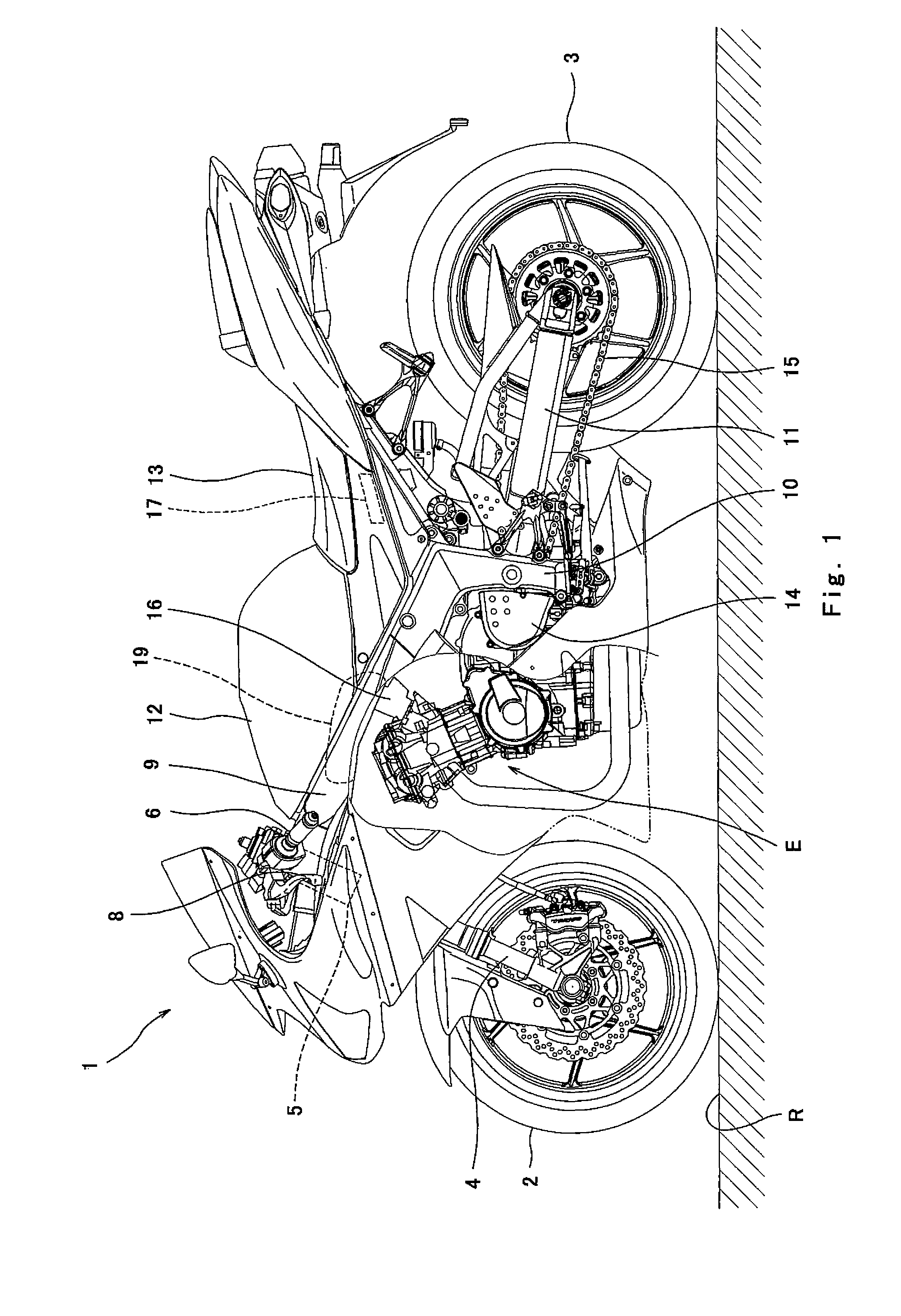
[0088]FIG. 1 is a left side view of a motorcycle 1 having a slip suppression function according to Embodiment 1 of the present invention. As shown in FIG. 1, the motorcycle 1 (vehicle) includes a front wheel 2 and a rear wheel 3 which roll on a road surface R. The rear wheel 3 is a drive wheel and the front wheel 2 is a driven wheel. The front wheel 2 is rotatably mounted to a lower end portion of a front fork 4 extending substantially vertically. The front fork 4 is mounted to a steering shaft (not shown) via an upper bracket (not shown) provided at the upper end portion thereof and an under bracket (not shown) provided under the upper bracket. The steering shaft is rotatably supported by a head pipe 5. A bar-type handle 6 extending rightward and leftward is mounted to the upper bracket.
[0089]A throttle grip 7 (see FIG. 2) of the handle 6 which is gripped by the driver's right hand is a throttle input device which is rotated by a gripping operation of the driver's wrist to operate ...
embodiment 2
[0162]FIG. 21 is a flowchart of a switch-OFF control process according to Embodiment 2 of the present invention. In this embodiment, in the switch-OFF control process, the termination of the traction control is not deferred unlike the example shown in FIG. 20. As shown in FIG. 21, it is determined whether or not the driver has turned OFF the traction control ON / OFF switch 40 (step S80). If it is determined that the driver has turned OFF the traction control ON / OFF switch 40, it is determined whether or not the traction control is being executed (step S81). If it is determined that the traction control is not being executed, the traction control function is set to be disenabled (step S84).
[0163]On the other hand, if it is determined that the traction control is being executed, it is determined whether or not the throttle valve opening degree detected by the throttle valve position sensor 25 is a closing threshold THc or smaller (step S82). If it is determined that the throttle valve ...
embodiment 3
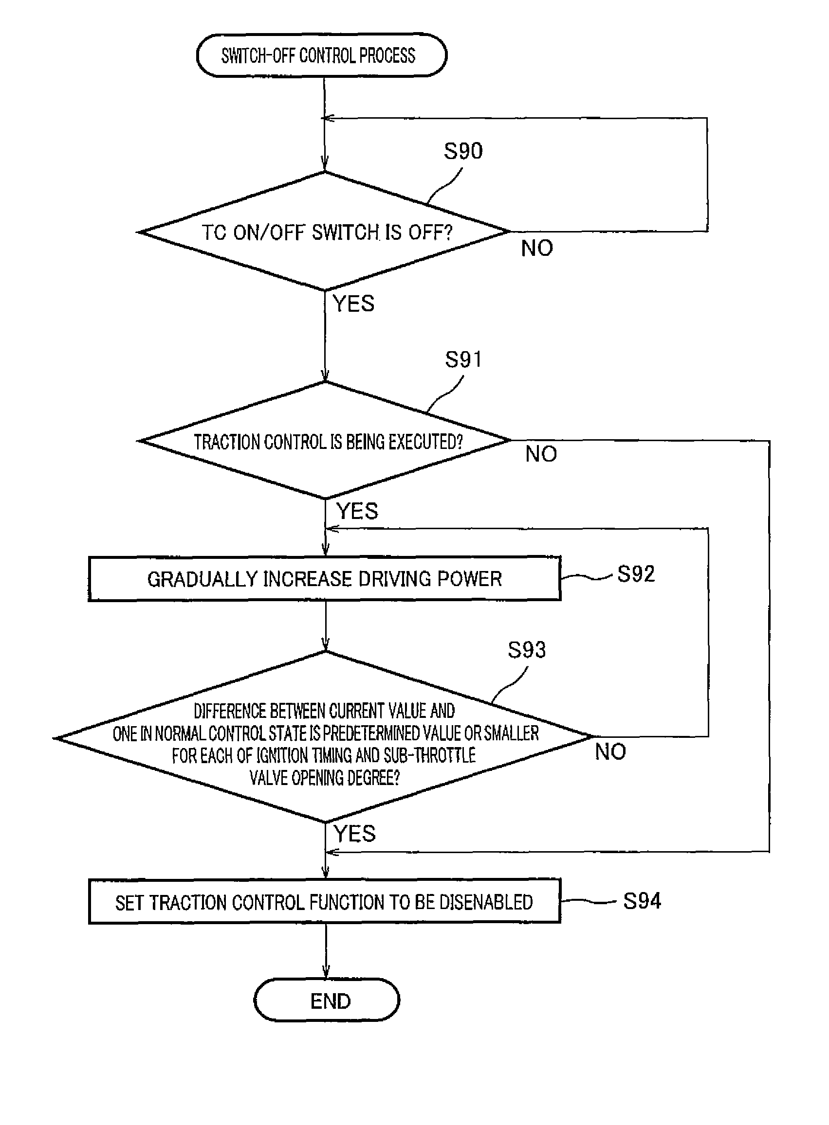
[0165]FIG. 22 is a flowchart of a switch-OFF control process according to Embodiment 3 of the present invention. As shown in FIG. 22, it is determined whether or not the driver has turned OFF the traction control ON / OFF switch 40 (step S90). If it is determined that the driver has turned OFF the traction control ON / OFF switch 40, it is determined whether or not the traction control is being executed (step S91).
[0166]If it is determined that the traction control is not being executed, the traction control function is set to be disenabled (step S94). On the other hand, if it is determined that the traction control is being executed, the driving power which has been reduced under the traction control is gradually increased (step S92). To be specific, the ignition timing and the sub-throttle valve opening degree which are the first parameters having been changed under the traction control are made gradually closer to the ones in the normal control state. Then, it is determined whether o...
PUM
 Abstract
Description
Claims
Application Information