Hydraulic power assisted diverter of circulating ball with floatable piston

A technology of hydraulic power steering and recirculating ball, applied in the direction of fluid steering mechanism, etc., can solve the problems of stuck steering gear, poor flow ability of piston steel ball, poor coaxiality of screw screw raceway and piston screw raceway, etc. To achieve the effect of eliminating steering hairpins, good driving feeling, and simple tooling

Inactive Publication Date: 2013-03-06
HANGZHOU SHIBAO AUTO STEERING GEAR
View PDF12 Cites 4 Cited by
  • Summary
  • Abstract
  • Description
  • Claims
  • Application Information

AI Technical Summary

Problems solved by technology

[0004] However, this structure also has the following disadvantages at the same time: 1: The manufacturing process of the spiral raceway is complicated; 2: The accumulation of machining errors may lead to poor coaxiality between the screw spiral raceway and the piston spiral raceway during assembly, which reduces the steel ball The flow ability makes the driver feel heavy when turning the direction; 3: With the increase of oil pressure, the interaction force between the rack on the piston and the tooth fan on the rocker shaft increases, and the piston warps and even deforms to make the steel The flow ability of the ball deteriorates, causing the driver to feel heavy when turning the direction, and in serious cases, the steering gear is stuck, causing major safety accidents
Especially the third one seriously restricts the development of large cylinder diameter recirculating ball hydraulic power steering machine

Method used


Image

  • Hydraulic power assisted diverter of circulating ball with floatable piston
  • Hydraulic power assisted diverter of circulating ball with floatable piston
  • Hydraulic power assisted diverter of circulating ball with floatable piston

Examples


Embodiment Construction

[0016] Describe the present invention in detail below in conjunction with accompanying drawing:

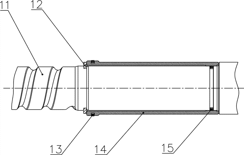
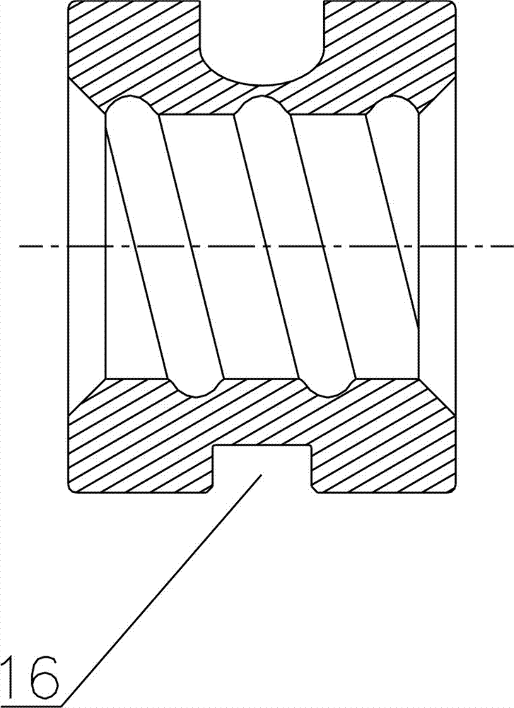
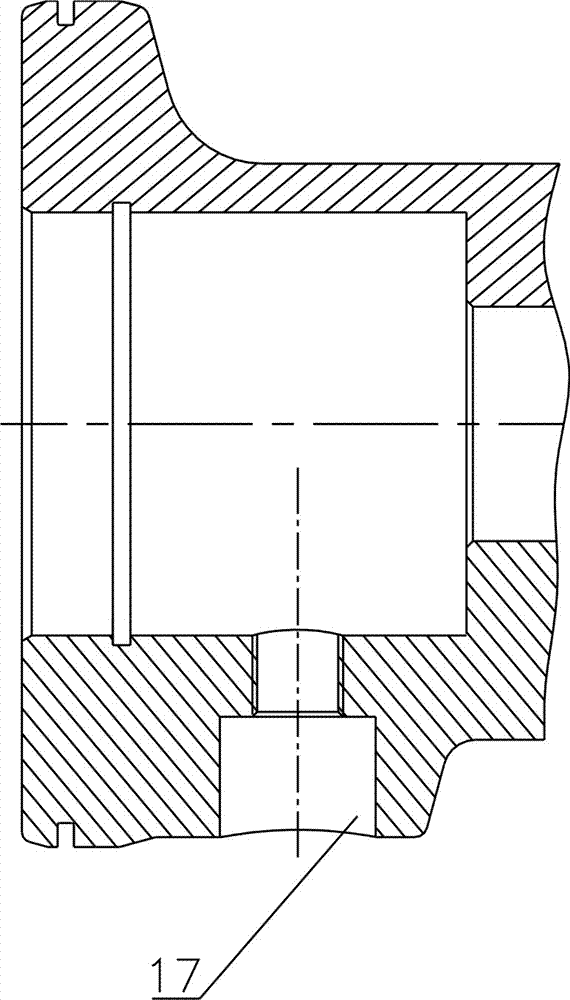
[0017] As shown in the figure, a recirculating ball hydraulic power steering device with a floating piston of the present invention mainly includes a valve assembly 1 , a rack piston 2 , a housing 18 and an output shaft 19 . The valve assembly 1 is provided with a screw rod 11, and the rack piston 2 is sleeved on the screw rod 11. A sealing sliding sleeve 14 is provided between the end of the rack piston 2 close to the valve assembly 1 and the screw rod 11 , and a nut 4 is provided between the other end of the rack piston 2 and the screw rod 11 . Such as figure 2 As shown, a sealing ring 15 is provided between the screw rod 11 and the sealing sliding sleeve 14 for sealing, and a sealing ring 13 is provided between the sealing sliding sleeve 14 and the rack piston 2 for sealing. A C-shaped snap ring 12 is also provided at the end of the sealing sliding sleeve 14 . Such as figu...


PUM


Abstract

The invention discloses a hydraulic power assisted diverter of a circulating ball with a floatable piston. The hydraulic power assisted diverter of the circulating ball with the floatable piston comprises a valve assembly, a rack piston, a shell and an output shaft. The valve assembly is provided with a screw, and the rack piston is sleeved on the screw. The hydraulic power assisted diverter of the circulating ball with the floatable piston is characterized in that a sealing sliding sleeve is arranged between the end of the rack piston close to the valve assembly and the screw, while a nut is arranged between the other end of the rack piston and the screw. The nut is in clearance fit with the rack piston, and the nut is fixedly arranged on the screw through a steel ball, a ball steel conduit and a conduit hoop. The nut rotates relative to the screw. According to hydraulic power assisted diverter of the circulating ball with the floatable piston provided by the invention, a spiral rollaway nest and the piston are processed independently, so that the hydraulic power assisted diverter of the circulating ball with the floatable piston is simple in process, and when the oil pressure is raised, the spiral rollaway nest is not easy to deform, and the flowing capacity of the steel ball does not deteriorate.

Description

technical field [0001] The invention relates to a vehicle steering device, in particular to a circulating ball hydraulic power steering device. Background technique [0002] The hydraulic power steering is installed at the front of the car near the driver's side. It can provide power assist and assist the driver to complete the steering function when the vehicle is turning. The power source of the hydraulic power steering is the engine, and when the engine is working, it drives the oil pump to work. When the high-pressure oil acts on the end surface (pressure bearing surface) of the piston, it generates thrust on the piston. As the oil pressure rises, the thrust increases. When the thrust increases enough to enable the steering wheel to overcome road resistance, the steering wheel is pushed to rotate, and the vehicle enters the steering state. [0003] The mechanical part of the recirculating ball hydraulic power steering gear is composed of the screw nut transmission pai...

Claims


Application Information

Patent Timeline
Patent Type & Authority Applications(China)
IPC IPC(8): B62D5/06B62D5/12
Inventor 吴琅平张宏伟邹理炎周文荣付松张宝义
Owner HANGZHOU SHIBAO AUTO STEERING GEAR
Why Eureka
Try Eureka