Wearable flexible upper limb exoskeleton assisting system
A power assist system and exoskeleton technology, applied in medical science, sports accessories, manipulators, etc., can solve problems such as poor flexibility, poor adaptability, and large size, and achieve the effect of large workload, light weight, and reduced volume and quality
- Summary
- Abstract
- Description
- Claims
- Application Information
AI Technical Summary
Problems solved by technology
Method used
Image
Examples
specific Embodiment approach 1
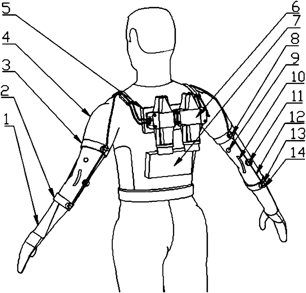
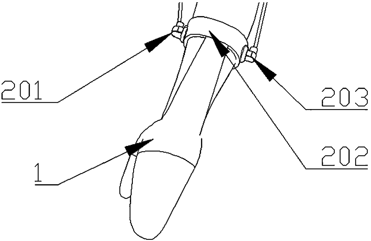
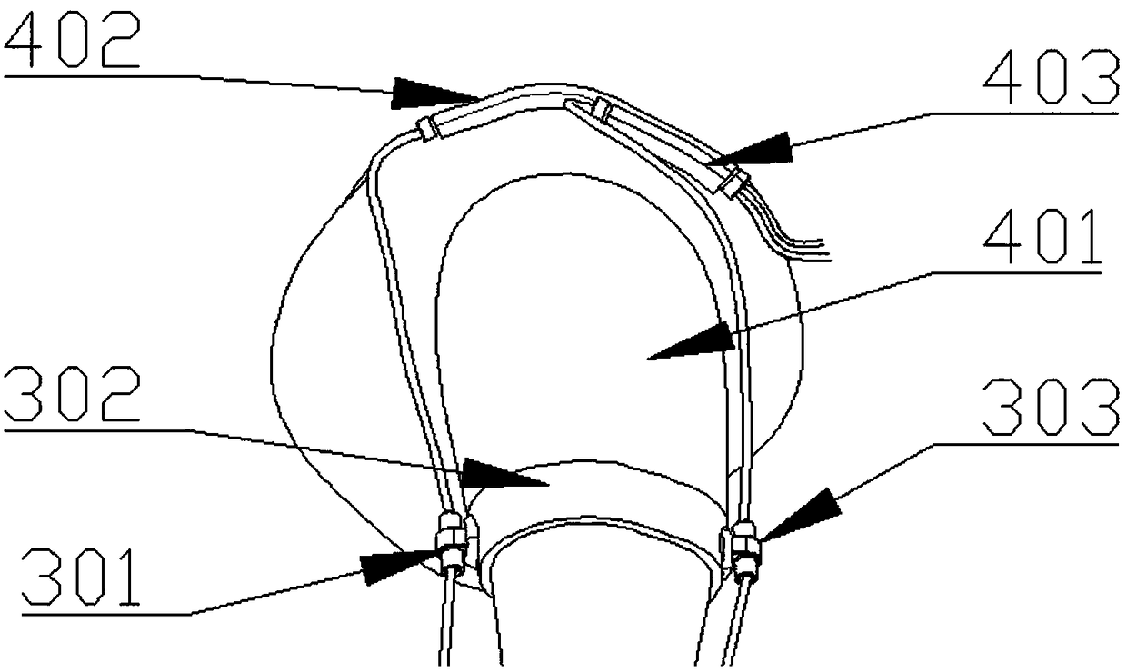
[0046] Specific implementation mode one: as Figure 1-10 As shown, the wearable flexible upper extremity exoskeleton assisting system of this embodiment includes a wearable suit, a control box 7, a transmission device, a sensor and two driving devices 6, and the wearable suit includes a soft vest 4, a rigid backboard 5, two The fixed glove 1, two forearm straps 2 and two large arm straps 3, the rigid backboard 5 is sewn on the back of the soft vest 4, and the wearer's forearm wears the fixed glove 1 and the forearm strap 2, The wearer wears a big arm strap 3 on his big arm, each forearm strap 2 is stitched and connected with the corresponding fixed glove 1, and the big arm strap 3 is sewn symmetrically on both sides of the soft vest 4;
[0047] Forearm strap 2 includes forearm anchor point 14 and forearm fixing band 202, forearm anchor point 14 includes forearm inner anchor point 201 and forearm outer anchor point 203, forearm inner anchor point 201 and forearm outer anchor po...
specific Embodiment approach 2
[0056] Specific implementation mode two: as Figure 5 and Figure 6 As shown, each driving device 6 in this embodiment includes a driving device housing 606, a brake 601, a Bowden wire pretensioning assembly 607, a driving device main shaft 609, a driving device housing cover 608, a rigid coupling 612, and a brushless motor 613, two electromagnetic clutches 602, two connectors 610, two harmonic reducers 603 and two wire wheels 605; the brushless motor 613 is fixed on one end of the drive device housing 606, and the output of the brushless motor 613 The shaft is fixedly connected to one end of the drive device main shaft 609 through a rigid coupling 612, the drive device main shaft 609 is mounted on the drive device housing 606 through two first deep groove ball bearings 23, and the other end of the drive device main shaft 609 passes through the brake 601 Installed on the other end of the drive device housing 606, the electromagnetic clutch 602 includes an armature rotor and a...
specific Embodiment approach 3
[0064] Specific implementation mode three: as Figure 8 and Figure 9 As shown, the wire wheel 605 in this embodiment is provided with a wire wheel joint slot 11-1 and a wire wheel winding slot 11-2, and the fixed end of the Bowden wire 12 is connected to the wire wheel joint slot 11-1, and each wire A Bowden wire 12 is wound in the wheel winding slot 11-2. With such a design, the Bowden wire 12 can be fixed at the slot 11-1 of the spool joint, and then wound in the spool winding slot 11-2. Other components and connections are the same as those in the second embodiment.
PUM
 Abstract
Description
Claims
Application Information
 - R&D
- Intellectual Property
- Life Sciences
- Materials
- Tech Scout
- Unparalleled Data Quality
- Higher Quality Content
- 60% Fewer Hallucinations
Browse by: Latest US Patents, China's latest patents, Technical Efficacy Thesaurus, Application Domain, Technology Topic, Popular Technical Reports.
© 2025 PatSnap. All rights reserved.Legal|Privacy policy|Modern Slavery Act Transparency Statement|Sitemap|About US| Contact US: help@patsnap.com


