Device for monitoring out-of-control falling of lifting equipment

A lifting device, No. 1 technology, applied in the direction of lifts, transportation and packaging, etc., can solve the problems of large consumption of materials, complicated installation, high cost, etc., and achieve the effect of low cost, simple structure and small volume

Inactive Publication Date: 2013-01-02
SHANGHAI WEIPINLAI ELECTROMECHANICAL TECH
View PDF6 Cites 4 Cited by
  • Summary
  • Abstract
  • Description
  • Claims
  • Application Information

AI Technical Summary

Problems solved by technology

This method of using a mechanical speed limiter requires mechanical mechanisms such as steel wires, pulleys, centrifugal arms, and springs. The length of the steel wires is proportional to the h

Method used


Image

  • Device for monitoring out-of-control falling of lifting equipment
  • Device for monitoring out-of-control falling of lifting equipment

Examples


Embodiment 1

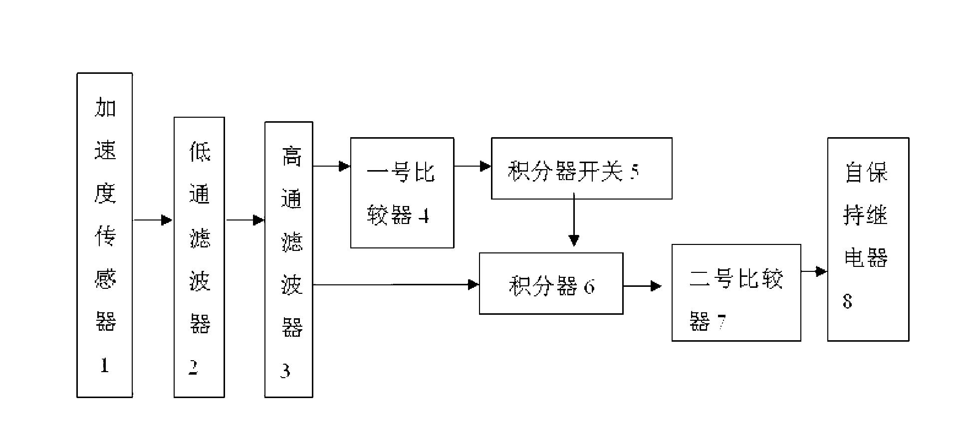
[0021] Such as figure 1 As shown, the device for monitoring the uncontrolled fall of lifting equipment provided in this embodiment includes an acceleration sensor 1, a low-pass filter 2 for filtering out high-frequency components, a high-pass filter 3 for filtering out DC and temperature drift signals, and a No. 1 Comparator 4, integrator 6, No. 2 comparator 7 and the self-holding relay 8 of locking fault state, the output end of described acceleration sensor 1 is connected with the input end of low-pass filter 2, the output end of low-pass filter 2 Connected to the input terminal of the high-pass filter 3, one output of the high-pass filter 3 is connected to the integrator 6 through the first comparator 4, the other output is directly connected to the integrator 6, and the output terminal of the integrator 6 is connected to the second comparator 7 is connected to the input end, the output end of the second comparator 7 is connected to the input end of the self-holding relay 8...

Embodiment 2

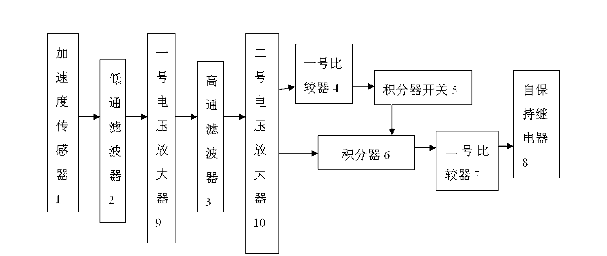
[0025] Such as figure 2 As shown, the difference between the device for monitoring the uncontrolled fall of lifting equipment provided in this embodiment and the embodiment 1 is only that a voltage amplifier 9 is connected in series between the low-pass filter 2 and the high-pass filter 3, and the The second voltage amplifier 10 is connected in series behind the high-pass filter 3; the rest of the content is the same as that described in Embodiment 1.

[0026] The working process of the device for monitoring the uncontrolled fall of lifting equipment described in this embodiment is as follows:

[0027] After the output signal of the acceleration sensor 1 is filtered by the low-pass filter 2 to remove high-frequency components, it is amplified by the No. 1 voltage amplifier 9, and then the high-pass filter 3 is used to filter out the DC and temperature drift signals to obtain a pure signal of the reaction acceleration; the pure The signal enters the No. 1 comparator 4 and the...


PUM


Abstract

The invention discloses a device for monitoring out-of-control falling of lifting equipment. The device comprises an acceleration sensor, a low-pass filter, a high-pass filter, a first comparator, an integrator, a second comparator and a latching relay, wherein an output terminal of the acceleration sensor is connected with an input terminal of the low-pass filter; an output terminal of the low-pass filter is connected with an input terminal of the high-pass filter; one path of output of the high-pass filter is connected with the integrator through the first comparator; another path of output of the high-pass filter is directly connected with the integrator; an output terminal of the integrator is connected with an input terminal of the second comparator; an output terminal of the second comparator is connected with an input terminal of the latching relay; and an integrator switch is connected in series between the first comparator and the integrator. According to the device disclosed by the invention, a complex mechanical principle is replaced by using an acceleration principle, and thus the out-off-control falling monitoring of the lifting equipment such as elevators is realized. The device has the advantages of simple structure, small size, low cost, easiness in mounting and the like and has universality and practicality.

Description

technical field [0001] The invention relates to a fall monitoring device, in particular to a device for monitoring uncontrolled fall of lifting equipment such as elevators. Background technique [0002] Lifting equipment such as elevators involves personal safety issues. When the control system falls out of control, a set of independent detectors are required to detect it in time and brake immediately. In the prior art, a common solution is to use a mechanical speed limiter, that is, when the car is running, the steel wire connected to it drives the speed limiter pulley to rotate. When the speed is higher than the threshold value, the centrifugal arm on the pulley touches Touch the safety switch to give a fall signal. This method of using a mechanical speed limiter requires mechanical mechanisms such as steel wires, pulleys, centrifugal arms, and springs. The length of the steel wires is proportional to the height of the floor, which requires a lot of material consumption. ...

Claims


Application Information

Patent Timeline
IPC IPC(8): B66B5/02
Inventor 吴攀洪浩王伟峰
Owner SHANGHAI WEIPINLAI ELECTROMECHANICAL TECH
Why Eureka
Try Eureka