Motorcycle cushion lock mechanism

A seat cushion lock, motorcycle technology, applied to bicycle locks, building locks, locks, etc., can solve the problems of misalignment of the lock cylinder, difficulty in controlling the accuracy of the installation position, and difficult assembly, so as to achieve smooth and fast assembly Effect

Active Publication Date: 2014-08-27
CHONGQING CONSTR ELECTROMECHANICAL CO LTD
View PDF4 Cites 0 Cited by
  • Summary
  • Abstract
  • Description
  • Claims
  • Application Information

AI Technical Summary

Problems solved by technology

The disadvantage of this structure is: when assembling, the locking mechanism part is installed first, and then the lock body must pass through the pre-set mounting hole on the cover, resulting in relatively long shafts for the lock body and small manufacturing errors at the frame installation It will be enlarged; there are generally many connection points between the cover itself and the frame, and it is difficult to control the accuracy of the installation position
Therefore, there are often errors in the fit between the lock body and the mounting hole reserved for the cover during installation, resulting in problems such as misalignment of the lock cylinder when the lock body passes through the cover, skewed lock body, and even difficulty in assembly.
If the assembly is forced, there will be assembly quality problems such as the displacement of the cover part, which will cause the gap between the cover part and other components such as taillights to become larger or the gap will be uneven, which will seriously affect the appearance quality of the vehicle and the performance of the seat cushion lock.

Method used


Image

  • Motorcycle cushion lock mechanism

Examples


Embodiment Construction

[0014] The present invention will be further described in detail below in conjunction with the accompanying drawings and specific embodiments.

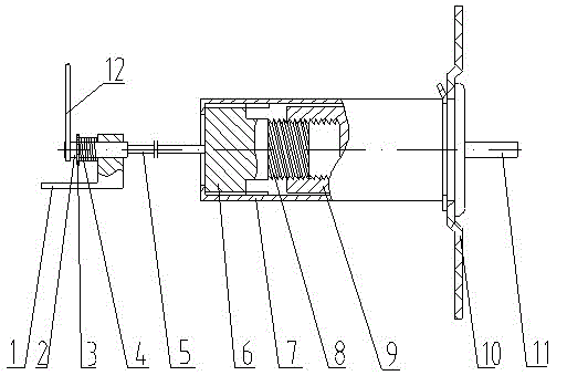
[0015] In specific implementation, such as figure 1 As shown, a motorcycle seat cushion lock mechanism includes a lock body part structure and a locking part structure that are arranged oppositely, the lock body part structure is fixed on the cover 10, and the locking part structure is fixed on the vehicle frame , wherein a straightened flexible pull cord 5 is arranged between the lock body part structure and the locking part structure, and when the lock core of the lock body part structure is turned by the key 11, the lock bar of the lock part structure can be pulled by the flexible stay cord 5 2.

[0016] Wherein, the partial structure of the lock body includes a cylindrical lock case 7 fixed on the cover, the outer end of the lock case 7 passes through the cover 10 and the lock cylinder 9 is arranged inside the outer end, and the ...


PUM


Abstract

The invention discloses a motorcycle cushion lock mechanism which comprises a lock body portion structure and a lock-up portion structure which are oppositely arranged. The lock body portion structure is fixed on a covering part and the lock-up portion structure is fixed on a frame. The motorcycle cushion lock mechanism is characterized in that a straightened flexible drawing cord is arranged between the lock body portion structure and the lock-up portion structure, and a lock cylinder of the lock body portion structure can draw a lock bar of the lock-up portion structure through the flexible drawing cord when rotated by a key. According to the motorcycle cushion lock mechanism, the force transmission and acting mode of the motorcycle cushion lock mechanism during the locking and unlocking is changed, and the flexible drawing cord is utilized to be connected between the lock body portion structure and the lock-up portion structure to transmit forces, accordingly, effects of installation errors on the assembly and the usage are avoided, assembly difficulties are decreased, the assembly quality is improved, the assembly time is shortened, and the reliability of final products is guaranteed.

Description

technical field [0001] The invention relates to a seat cushion lock structure of a curved beam motorcycle and a scooter. Background technique [0002] In current underbone motorcycles and scooters, a seat box is generally provided under the seat cushion for placing articles, one end of the seat cushion is hinged to the upper port of the seat cushion box and serves as a box cover, and a seat is provided at the other end of the seat cushion. The pad lock structure makes it easy to lock the seat box. [0003] The seat cushion lock structure of the existing curved beam motorcycle and scooter includes the seat cushion lock body and the seat cushion lock mechanism, and the seat cushion lock body and the seat cushion lock mechanism all form a hard connection in the form of a shaft, that is, in the assembly Usually, one end of the seat cushion locking mechanism is assembled on the frame outside the seat cushion box and covered by the cover of the vehicle body, and the connecting sh...

Claims


Application Information

Patent Timeline
Patent Type & Authority Patents(China)
IPC IPC(8): E05B71/00
Inventor 周明强
Owner CHONGQING CONSTR ELECTROMECHANICAL CO LTD
Why Eureka
Try Eureka