LED (Light Emitting Diode) radiating baseplate and manufacturing method thereof

A technology of light-emitting diodes and heat-dissipating substrates, used in electrical components, circuits, semiconductor devices, etc.

Inactive Publication Date: 2013-02-13
陈 一璋
View PDF3 Cites 0 Cited by
  • Summary
  • Abstract
  • Description
  • Claims
  • Application Information

AI Technical Summary

Problems solved by technology

[0008] The present inventor considers that there is insulating glue between the LED and the heat-conducting substrate body in the existing heat-dissipating substrate, so that the heat cannot be quickly transferred from the LED to the heat-dissipating substrate , so it will still cause the loss of LED and reduce the service life. Therefore, the inventor invented the light-emitting diode (LED) heat dissipation substrate and its manufacturing method by virtue of its rich knowledge background and years of research.

Method used


Image

  • LED (Light Emitting Diode) radiating baseplate and manufacturing method thereof
  • LED (Light Emitting Diode) radiating baseplate and manufacturing method thereof
  • LED (Light Emitting Diode) radiating baseplate and manufacturing method thereof

Examples


Embodiment Construction

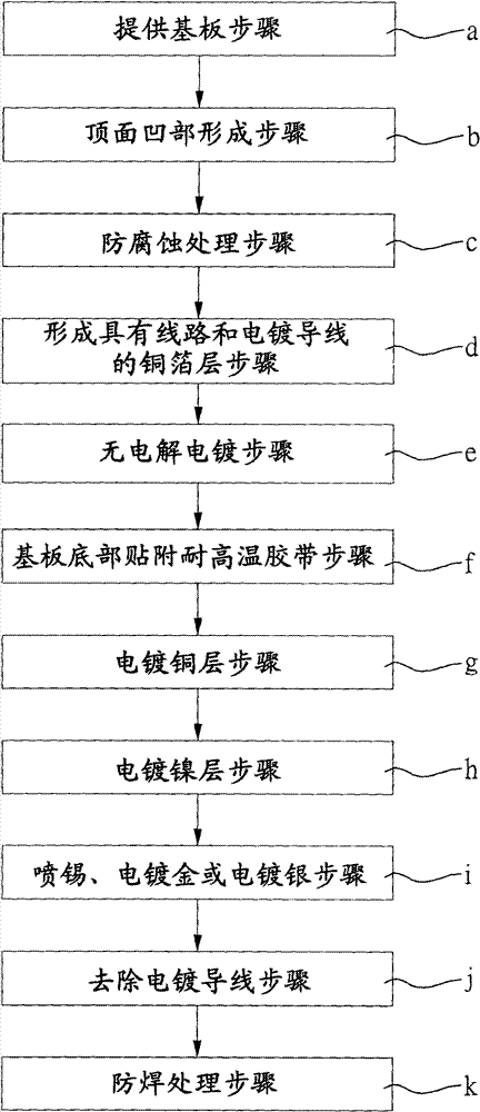
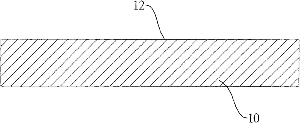
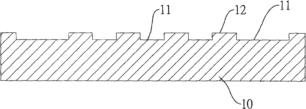
[0053] In order to further explain the technical means and effects of the present invention to achieve the intended purpose of the invention, below in conjunction with the accompanying drawings and preferred embodiments, the specific implementation, structure, The manufacturing method, steps, features and effects thereof are described in detail below.

[0054] The aforementioned and other technical contents, features and effects of the present invention will be clearly presented in the following detailed description of preferred embodiments with reference to the drawings. Through the description of the specific implementation mode, when the technical means and functions adopted by the present invention to achieve the predetermined purpose can be obtained a deeper and more specific understanding, but the accompanying drawings are only for reference and description, and are not used to explain the present invention be restricted.

[0055] The "electroless plating" described her...


PUM

PropertyMeasurementUnit
thicknessaaaaaaaaaa
depthaaaaaaaaaa
thicknessaaaaaaaaaa

Abstract

The invention relates to an LED (Light Emitting Diode) radiating baseplate and a manufacturing method thereof. The manufacturing method of the LED radiating baseplate comprises the following steps of: providing a heat conductive metal baseplate which can be a heat conductive aluminum baseplate or a heat conductive copper baseplate; forming a plurality of concave parts on the top surface of the heat conductive metal baseplate, and screenprinting insulating glue in the concave parts; forming a copper foil layer with circuits and electroplate leads on the top surface of the heat conductive metal baseplate, exposing the top surface of the heat conductive metal baseplate, which does not have the insulating glue and is an area used for subsequent packaging; forming a chemical nickel layer on the metal surface exposed to the outside in an electrolysis-free electroplating way; attaching a high-temperature resistant adhesive tape to the bottom of the heat conductive metal baseplate, and then forming a metal layer on the nickel layer on the top surface ; removing the electroplate leads, and then performing solder mask treatment to finally obtain the LED radiating baseplate. Since no insulating glue exists between the heat conductive metal baseplate and an LED, heat can be conducted to the heat conductive metal baseplate quickly, light attenuation caused by high temperature generated by the LED can be avoided, and the service life of the LED can be prolonged.

Description

technical field [0001] The present invention relates to a method for manufacturing a light-emitting diode (LED) heat dissipation substrate, in particular to a light-emitting diode heat dissipation substrate on which insulating glue can be provided only on non-encapsulation areas by screen printing on a heat-conducting metal substrate, so that There is no insulating glue between the LED and the heat-conducting metal substrate, so that the LED can quickly remove heat. Background technique [0002] With the development of the light-emitting diode (LED) industry, in order to meet the market demand, the number of LEDs in a package has been greatly increased, and the luminous power of LEDs is also gradually improving. However, such changes have brought about accumulation of heat. When the heat cannot be effectively dissipated from the LED package, so the temperature of the LED grain is too high, it will inevitably lead to the phenomenon of "light decay", that is, the signal of l...

Claims


Application Information

Patent Timeline
Patent Type & Authority Patents(China)
IPC IPC(8): H01L33/00
Inventor 陈一璋
Owner 陈 一璋
Why Eureka
Try Eureka