Light emitting module

A light-emitting module and light-emitting element technology, which is applied in the direction of electrical components, electric solid-state devices, circuits, etc., can solve problems such as poor performance, easy accumulation of heat energy in semiconductor light-emitting elements, and influence of semiconductor light-emitting elements on luminous efficiency and luminous life, so as to avoid light Fading, reliability and service life improvement effect

Active Publication Date: 2013-12-04
LIGITEK ELECTRONICS
View PDF7 Cites 6 Cited by
  • Summary
  • Abstract
  • Description
  • Claims
  • Application Information

AI Technical Summary

Problems solved by technology

[0003] As the power of semiconductor light-emitting elements increases, the heat energy emitted by them gradually increases. For example, only 15-20% of the output power of a high-power light-emitting diode (high power LED) greater than 1W is converted into light. The remaining 80~85% is converted into heat energy. If the heat energy cannot be effectively conducted to the outside world, the interface temperature of the semiconductor light-emitting element will be too high, which will affect the luminous efficiency and luminous life.
[0004] In addition, at present, technicians have used semiconductor light-emitting elements with transparent flexible light guide substrates to achieve large-angle lighting effects with both uniformity and softness. However, transparent flexible light guide substrates cannot effectively conduct heat or have poor heat dissipation efficiency. , which makes the semiconductor light-emitting element easy to accumulate heat energy

Method used


Image

  • Light emitting module
  • Light emitting module
  • Light emitting module

Examples


Embodiment 1

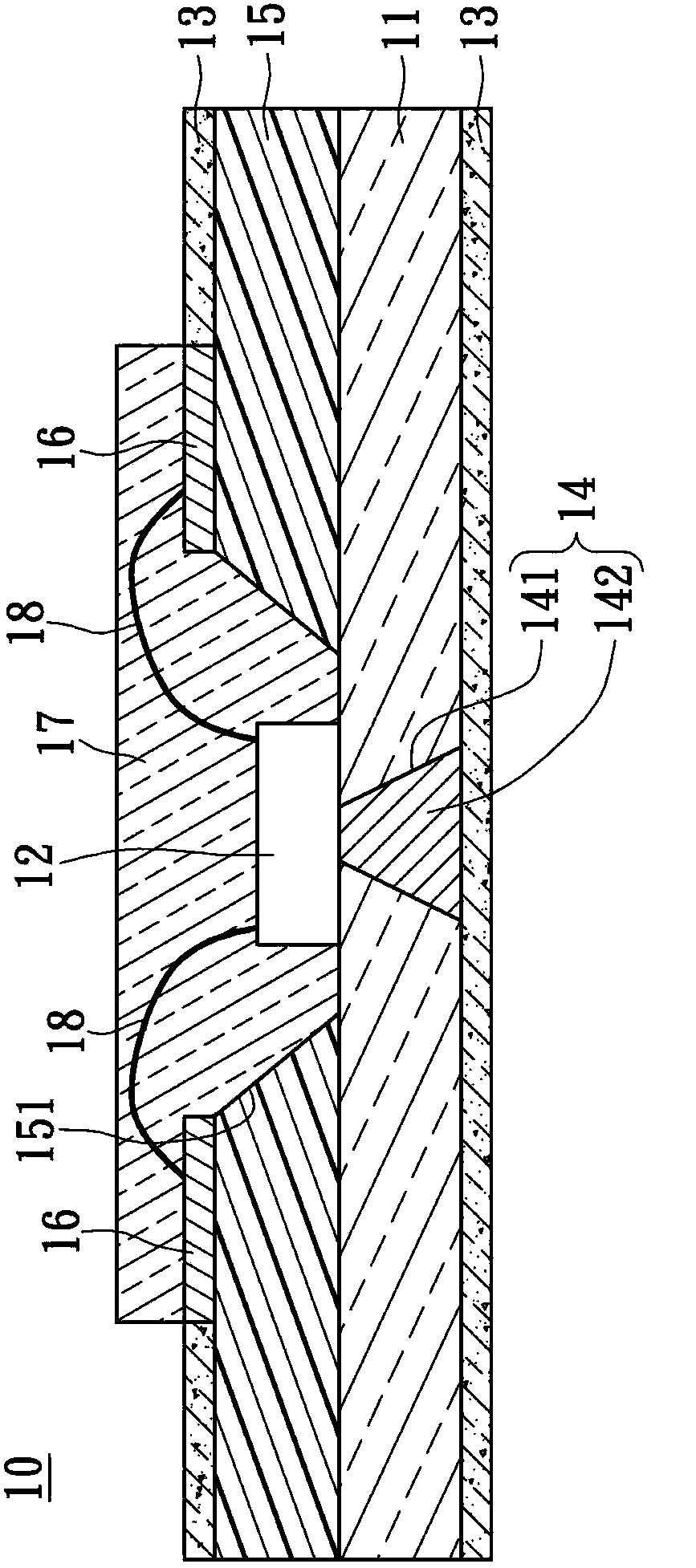
[0045] see figure 1 , figure 1 It is a cross-sectional view of the light emitting module 10 according to the first embodiment of the present invention. The light-emitting module 10 includes a transparent and flexible light-guiding substrate 11 , at least one light-emitting element 12 , a light-guiding and heat-dissipating layer 13 , and at least one vertical heat-conducting structure 14 .

[0046] The transparent flexible light guide substrate 11 has an upper surface and a lower surface, and the transparent flexible light guide substrate 11 has a first refractive index. The light emitting element 12 is disposed on the upper surface of the transparent flexible light guide substrate 11, so that the light emitting element The light emitted by 12 is projected toward the upper surface and the lower surface. The light guide and heat dissipation layer 13 is arranged on the lower surface of the transparent and flexible light guide substrate 11, and the light guide heat dissipation la...

Embodiment 2

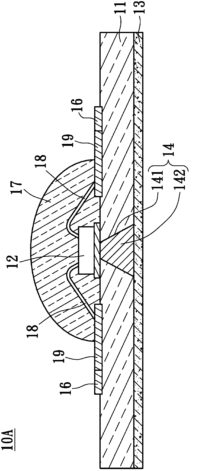
[0058] see figure 2 , figure 2 This is a cross-sectional view of the light-emitting module 10A according to the second embodiment of the present invention. The difference from the previous embodiment is that, in order to make the light-emitting module 10A have a wide range of lighting effects, the light-emitting module 10A does not have a reflective base (not shown), but the outer surface of the lens layer 17 is a convex curved surface. In addition, the light emitting module 10A further includes a plurality of metal pads 19 . The circuit layer 16 and the plurality of metal pads 19 are disposed on the upper surface of the transparent flexible light guide substrate 11 and are electrically connected to each other.

[0059] Accordingly, the light emitting element 12 is disposed on the upper surface of the transparent flexible light guide substrate 11 , and is electrically connected to the metal pad 19 and the circuit layer 16 through the metal wire 18 , so that the circuit desi...

Embodiment 3

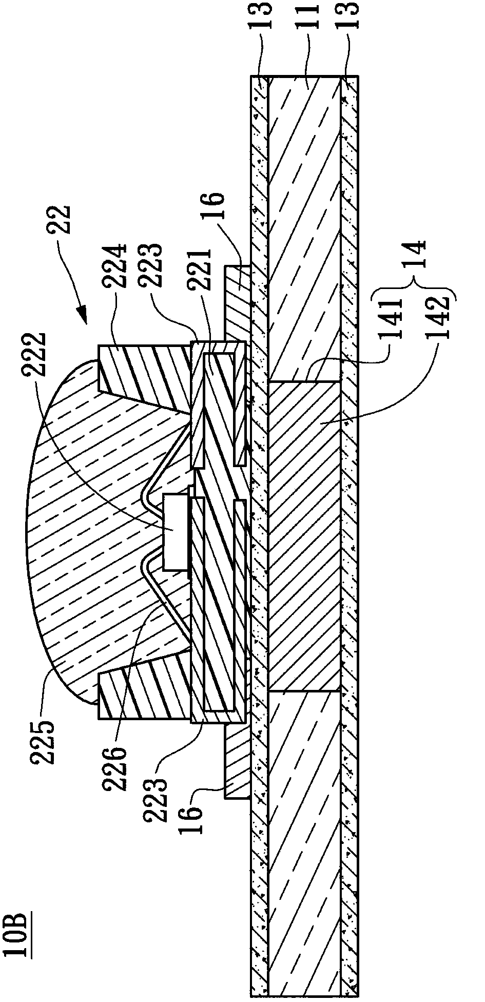
[0061] see image 3 , image 3 It is a cross-sectional view of the light-emitting module 10B according to the third embodiment of the present invention. The difference from the previous embodiment is that the light-emitting element 22 is an LED package, which includes a reflective base 221, a light-emitting diode chip 222, A plurality of metal brackets 223 , a reflection cup 224 and a lens layer 225 are provided.

[0062] The light-emitting diode chip 222 and a plurality of metal pads 223 are fixed on the reflection base 221, wherein each metal bracket 223 is U-shaped, and is respectively connected to the top, surface and one side of the reflection base 221. The light-emitting diode The chip 222 is electrically connected to the metal bracket 223 by means of metal wires 226 . The reflector cup 224 is disposed on the heat dissipation layer 221 and surrounds the LED chip 222 . The lens layer 225 covers the LED chip 222 , some metal pads 233 and metal wires 226 .

[0063] In add...


PUM


Abstract

The invention provides a light emitting module. The light emitting module comprises a transparent flexible light guide substrate, at least one light emitting member, a light guide heat dissipation layer and at least a vertical heat conduction structure, wherein the transparent flexible light guide substrate is provided with an upper surface and a lower surface; the light emitting member is arranged on the upper surface of the transparent flexible light guide substrate; the light guide heat dissipation layer is arranged on the lower layer of the transparent flexible light guide substrate; the vertical heat conduction structure is embedded in the transparent flexible light guide substrate for connection with the light emitting member and the light guide heat dissipation layer in a heat-conducting manner. According to the invention, the heat energy generated by the light guide member when the light guide member works is conducted to the light guide heat dissipation layer through the vertical heat conduction structure and is dissipated through the light guide heat dissipation layer, so that light attenuation generated due to an overheat light emitting module is prevented, thus the reliability and the service life of the light emitting module are improved.

Description

technical field [0001] The present invention relates to a light-emitting device, in particular to a light-emitting module with high heat dissipation efficiency. Background technique [0002] Semiconductor light-emitting devices (such as light-emitting diodes) have the advantages of power saving, small size and high brightness, so today's semiconductor light-emitting devices are widely used, such as key systems, backlight modules for mobile phone screens, vehicle lighting systems, and decorative lamps. It can be seen that semiconductor light-emitting elements are widely used in products such as remote control and remote control. [0003] As the power of the semiconductor light-emitting element increases, the heat energy it emits also gradually increases. For example, the output power of a high-power light-emitting diode (high power LED) greater than 1W is only 15~20% converted into light. The remaining 80-85% is converted into heat energy. If the heat energy cannot be effect...

Claims


Application Information

Patent Timeline
Patent Type & Authority Applications(China)
IPC IPC(8): H01L33/64
CPCH01L2224/48091H01L2924/181
Inventor 谢馨仪陈义文彭启峰童义兴
Owner LIGITEK ELECTRONICS
Why Eureka
Try Eureka