Wireless control device

A technology for wireless control equipment and equipment, applied in radio wave measurement systems, radio wave reflection/re-radiation, TV, etc., can solve problems such as limiting the working distance of remote control equipment and weak input signals

Inactive Publication Date: 2013-01-02
SIEMENS AG
View PDF7 Cites 1 Cited by
  • Summary
  • Abstract
  • Description
  • Claims
  • Application Information

AI Technical Summary

Problems solved by technology

However, this keyboard still requires a separate power supply located inside the keyboard, with the attendant proble

Method used


Image

  • Wireless control device
  • Wireless control device
  • Wireless control device

Examples


Embodiment Construction

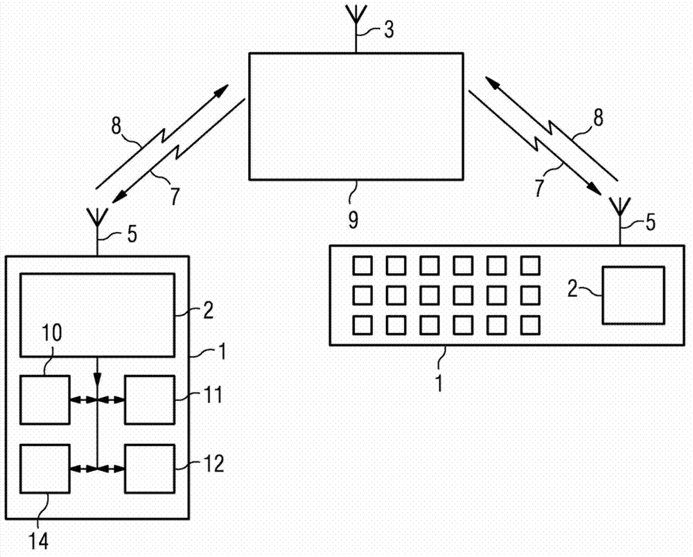
[0035] Many implementations of the invention are possible and a few examples of these are described below. figure 1 A basic arrangement of the invention is shown wherein a wireless control device 1 such as a computer keyboard, computer mouse, TV remote or wireless game controller is provided with a power harvesting circuit 2 in order to generate power for the wireless control device. The power harvesting circuit 2 converts energy in radio frequency (RF) signals received at the antenna 5 of the device 1 into power for controlling the device. The RF signal 7 is typically the signal sent from the antenna 3 on a host 9, such as a personal computer in the case of a keyboard or mouse, or a television in the case of a television remote control, but integrated in the host Or a single transmitter separate from the host could be used to cover devices within a certain range (eg in a study, office or home). For convenience, the transmitted signal is usually a microwave signal with a typi...


PUM


Abstract

A wireless control device (1) comprises an antenna (5) and a power harvester (2) to generate power for the device from a radio frequency signal (7) incident on the antenna. The device further comprises an upconverter stage; the upconverter stage comprising a first port (21) to receive a control signal (13) to be upconverted and a second port (34) to receive the incident radio frequency signal (7) and to output the upconverted control signal at upper and lower sideband frequencies (8). The antenna is coupled to the second port.

Description

technical field [0001] The present invention relates to a wireless control device, in particular for consumer electronics, such as personal computers or entertainment devices. Background technique [0002] Usually all remote control devices require their own power source (typically batteries). However, in addition to the nuisance to the user when the battery dies, there is the environmental concern and attendant expense of the large number of batteries that must be safely disposed of, both for the user and the manufacturer. [0003] Many schemes have been proposed in order to reduce the power consumption of these devices so that the batteries are not replaced as often, but this only reduces the problem rather than avoiding it. An example of this is US6507763 which mentions the use of radio frequency wireless keyboards instead of infrared keyboards because RF keyboards consume less power. It doesn't solve the hassle for the user of having to keep a lot of spare batteries of...

Claims


Application Information

Patent Timeline
IPC IPC(8): G08C17/02H04B1/40
CPCH04B5/00H04B1/408H04N5/44G08C2201/10G08C17/02H02J17/00H03F7/04H04B1/04H04B2001/0491G01S13/75G01S13/758G06K19/07786
Inventor P.贝斯利O.海德
Owner SIEMENS AG
Why Eureka
Try Eureka