Fuel cell electric power generator and management method thereof

A fuel cell and generator technology, applied in fuel cells, fuel cell additives, regenerative fuel cells, etc., can solve problems such as constrained polarization

Active Publication Date: 2013-01-02
依莱克托电能系统制造有限责任公司
View PDF2 Cites 0 Cited by
  • Summary
  • Abstract
  • Description
  • Claims
  • Application Information

AI Technical Summary

Problems solved by technology

However, since in practice the actual process is often highly irreversible and thus subject to polarization phenomena, it often occurs that the electrolyser needs to continuously deliver heat to the environment in order to maintain the required full load operation under temperature

Method used


Image

  • Fuel cell electric power generator and management method thereof
  • Fuel cell electric power generator and management method thereof

Examples


Embodiment Construction

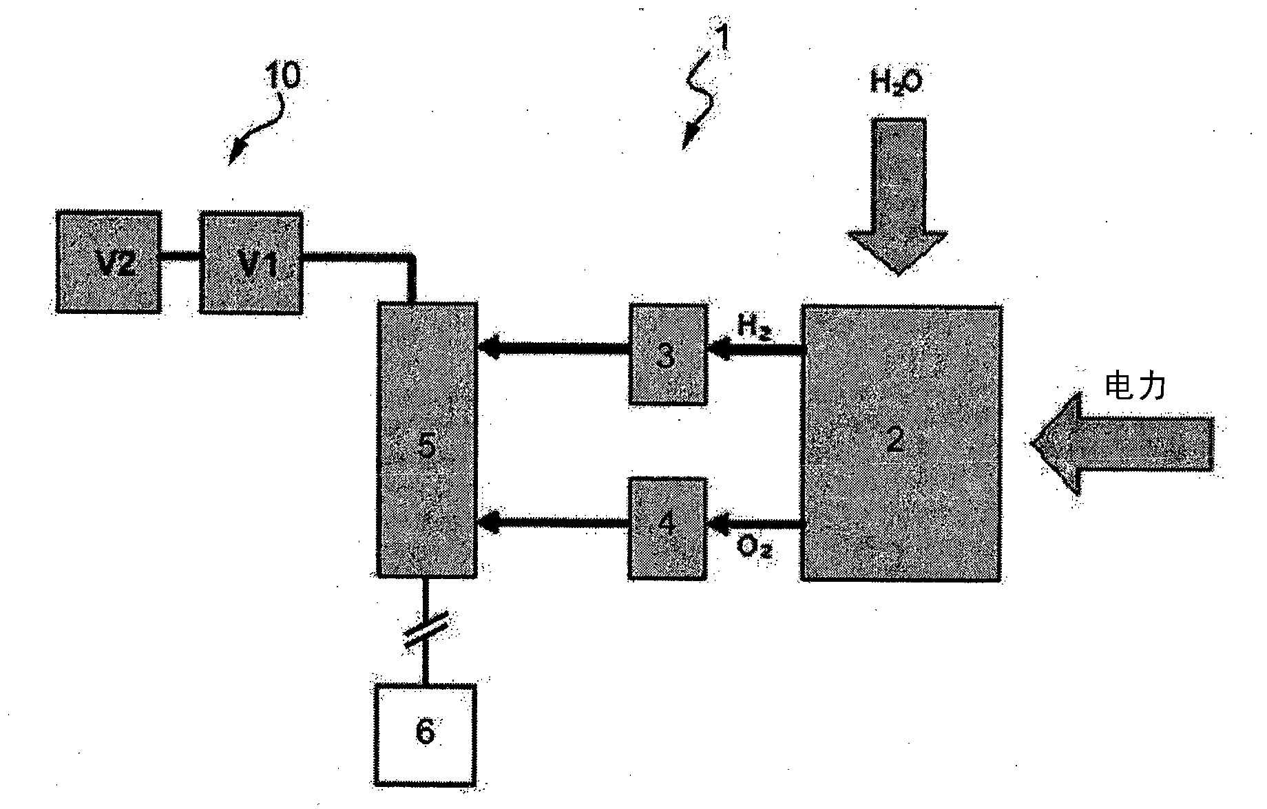
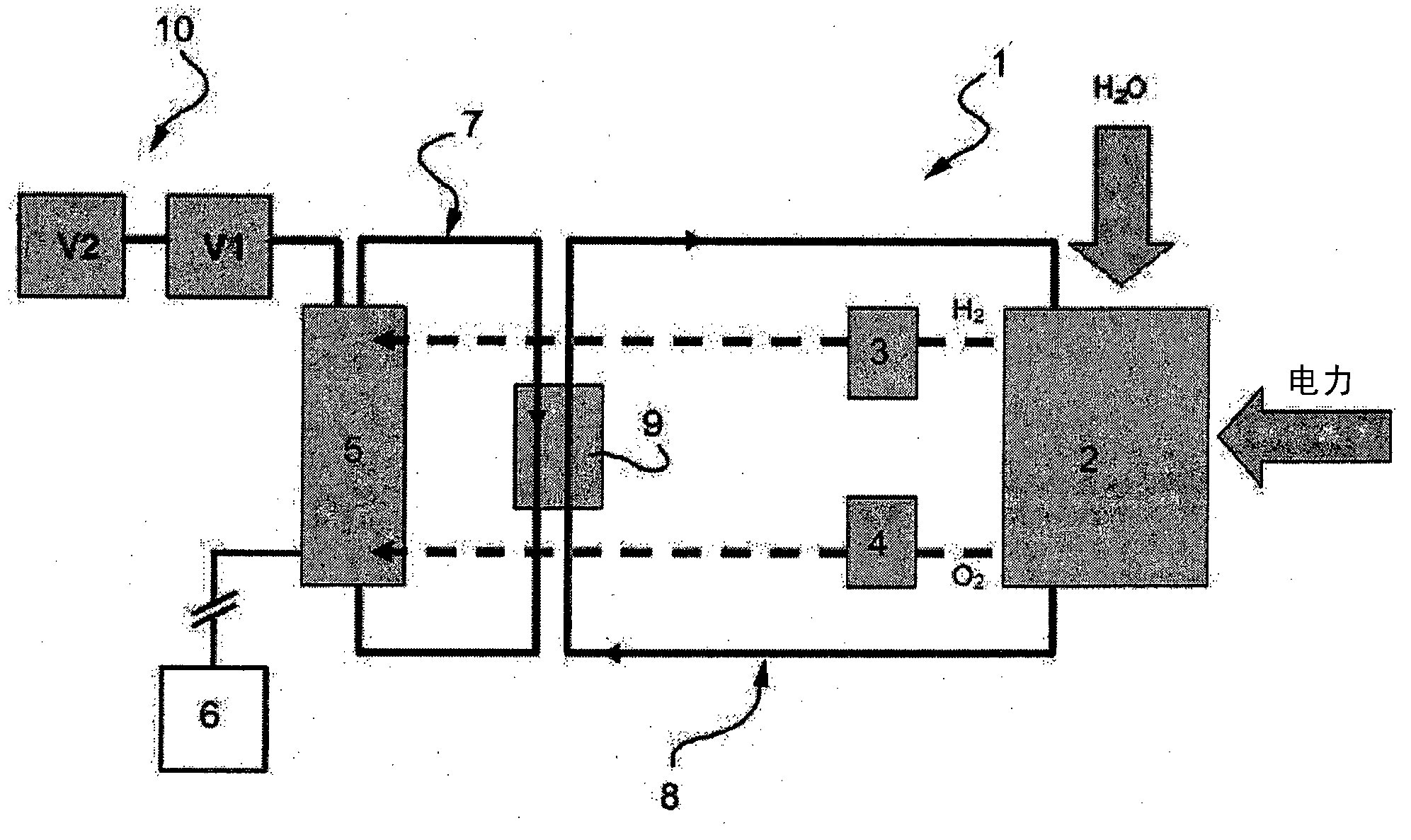
[0028] exist figure 2 In , reference numeral 1 denotes the whole of the fuel cell generator according to the present invention.

[0029] The generator 1 comprises a plurality of fuel cells stacked to form a stack 5 fluidically connected to the tanks 3, 4 which in use receive pure fuel cells from the tanks 3, 4 respectively. The gaseous fuel flow and the oxidizing gas flow are mixed in a gaseous state to generate electricity to be supplied to the load 6.

[0030] The generator 1 also includes field devices 2 for generating gaseous fuel to be supplied to the stack 5 .

[0031] In the example shown, the device 2 for generating gaseous fuel comprises an electrolyzer configured to receive electricity and water and convert the water into its two components: hydrogen and oxygen, which are stored in tanks respectively 3, 4 middle. Thus, the generator 1 uses hydrogen as a gaseous fuel and oxygen as an oxidizing gas.

[0032] The generator 1 advantageously comprises a hydraulic cir...


PUM


Abstract

The invention relates to an electric power generator (1) comprising a plurality of fuel cells stacked in a stack (5) and configured to supply an electric load (6), the generator (1) comprising means (2) for generating a gas fuel to be supplied to the stack (5), and means (7, 10) for removing at least part of a heat flow generated in the stack (5) as a consequence of the consumption of said, gas fuel; characterized in that it comprises heating means (8, 9) configured to maintain said means (2) for generating gas fuel within a predetermined temperature range and comprising means (9) for transferring at least part of said removed part of the heat flow generated in the stack (5) from said removing means (7) to said means (2) for generating gas fuel.

Description

technical field [0001] The invention relates to a fuel cell generator and a management method thereof. Background technique [0002] Fuel cell generators (UPS) for stationary use and with low capacity (5-20kW) are usually designed for backup applications, using PEM-type (Proton Exchange Membrane) fuel cells as a basis, which use Hydrogen as fuel. In other words, these systems operate in a near-constant state of operational "lethargy" (standby), but can be easily activated for very short The situation can ensure that the power demand of the load is met. [0003] Since, at least in principle, continuous and / or frequent use of these generators is not required, it is not cost-effective to install complex systems for storing and supplying hydrogen such as liquid hydrogen evaporation systems (where hydrogen is stored at cryogenic temperatures) benefit. [0004] In addition, the simplest systems for storage and supply most commonly used in the field, where the hydrogen is obtai...

Claims


Application Information

Patent Timeline
Patent Type & Authority Applications(China)
IPC IPC(8): H01M8/04H01M8/06H01M16/00H01M8/18
CPCH01M8/04365H01M8/0656H01M8/04373H01M8/04029H01M16/003H01M8/04738H01M8/04037H01M8/04768Y02E60/528H01M8/04776H01M8/04052Y02E60/50H01M8/186
Inventor 皮耶尔保罗·凯尔基朱塞佩·贾诺利奥克里斯蒂娜·普拉拉卢卡·巴尔迪尼西蒙娜·西尔温尼
Owner 依莱克托电能系统制造有限责任公司
Why Eureka
Try Eureka