
Railway vehicle ceiling plate mounting structure

A rail vehicle and installation structure technology, applied to the direction of the railway roof, etc., can solve the problems of simple installation, unsightly, low quality, etc., and achieve the effect of simple assembly, easy maintenance and replacement

Active Publication Date: 2013-01-09
CRRC NANJING PUZHEN CO LTD
View PDF4 Cites 2 Cited by
  • Summary
  • Abstract
  • Description
  • Claims
  • Application Information

AI Technical Summary

Problems solved by technology

In the past, the connection between the flat roof, the partition wall, and the flat roof was made of back wood lining or aluminum beams, and wood screws were placed directly on the surface. In order to cover the screws, pressure strips were used to cover the outside, which was unsightly and caused material waste; and The installation method of this structure is simple, the quality is low, and it is not convenient for the maintenance and replacement of the flat roof

Method used


Image

  • Railway vehicle ceiling plate mounting structure
  • Railway vehicle ceiling plate mounting structure

Examples


Embodiment Construction

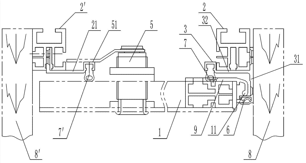
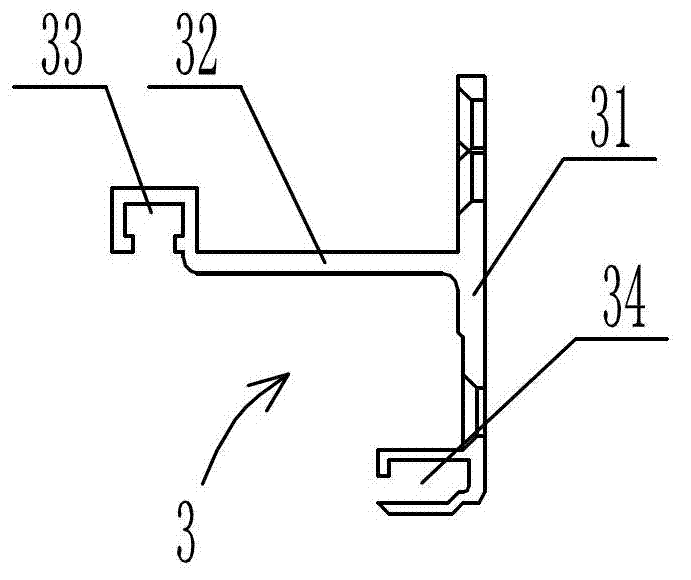
[0011] Such as figure 1 As shown, the installation structure of the flat roof plate of the rail vehicle in this embodiment consists of: the first partition wall 8 and the second partition wall 8' of the vehicle opposite to each other in parallel, the first flat roof frame 2, the second flat roof frame 2', and the The improvement of the flat roof 1 between a flat roof frame 2 and the second flat roof frame 2' is that it also includes a T-shaped first connecting piece 3 with a vertical plate 31 and a flat plate 32, and the first connecting piece 3 The vertical plate 31 is fixedly connected with the first partition wall 8 of the vehicle. The first flat roof frame 2 is placed on the flat plate 32 of the first connecting member 3 and fixedly connected by screws. The lower end of the vertical plate 31 of the first connecting member 3 has an opening facing the inside of the vehicle. The first groove 34, the first groove 34 is embedded with an adjustable rubber block 6, the first end ...


PUM


Abstract

The invention discloses a railway vehicle ceiling plate mounting structure, which comprises a ceiling plate skeleton, a ceiling plate and a first connecting piece, wherein the first connecting piece is fixedly connected with a vehicle dividing wall and the ceiling plate skeleton respectively; the lower end of the first connecting piece is provided with a first groove of which the opening faces to the inside of a vehicle; a regulating rubber block is embedded in the first groove; the first end of the ceiling plate is provided with a spindle which can be supported on the upper wall of the first groove and is used as a fulcrum to rotate; the inner end of the ceiling plate of the first connecting piece is provided with a second groove of which the opening faces downwards; a first compression rubber block is embedded in the second groove; the second end of the ceiling plate is fixed with a second ceiling plate skeleton through a compression lock; after the ceiling plate is installed, the upper surface of the ceiling plate is abutted by the first compression rubber block; and the side edge of the ceiling plate is supported by the regulating rubber block. According to the railway vehicle ceiling plate mounting structure, liner materials at the back of the mounting position of the original structure are omitted, the periphery of the ceiling plate is fixed by respectively a splicing lock and a compression lock, the appearance is free from obvious bolts or depression bars, and therefore, the railway vehicle ceiling plate mounting structure is attractive. In addition, the mounting structure is simple to assemble and is convenient to maintain and replace the ceiling plate.

Description

technical field [0001] The invention relates to a rail vehicle flat roof installation structure, which belongs to the technical field of rail vehicle interior decoration. Background technique [0002] The interior decoration of a passenger car is the main part that directly meets the passengers. Its design technology continues to develop with the development of vehicle technology, and its structural shape is directly related to the overall aesthetic effect of the car. In the past, the connection between the flat roof, the partition wall, and the flat roof was made of back wood lining or aluminum beams, and wood screws were placed directly on the surface. In order to cover the screws, pressure strips were used to cover the outside, which was unsightly and caused material waste; and The installation method of this structure is simple, the quality is low, and it is not convenient for the maintenance and replacement of the flat roof. Contents of the invention [0003] The tec...

Claims


Application Information

Patent Timeline
IPC IPC(8): B61D17/12
Inventor 陆丽芬王照杰高健飞王文平
Owner CRRC NANJING PUZHEN CO LTD
Learn More