Flapping wing and turning device of micro aerial vehicle

A micro-aircraft and steering device technology, applied in aircraft, transportation and packaging, helicopters, etc., can solve problems such as difficult miniaturization and complex structure, and achieve the effects of low manufacturing cost, simple control, and high transmission ratio

Inactive Publication Date: 2013-01-16
SOUTHEAST UNIV
View PDF7 Cites 29 Cited by
  • Summary
  • Abstract
  • Description
  • Claims
  • Application Information

AI Technical Summary

Problems solved by technology

Most of the existing flapping wings and steering devices have complex structures and are difficult to miniaturize

Method used


Image

  • Flapping wing and turning device of micro aerial vehicle
  • Flapping wing and turning device of micro aerial vehicle
  • Flapping wing and turning device of micro aerial vehicle

Examples


Embodiment Construction

[0025] The present invention will be further described below in conjunction with the accompanying drawings and specific embodiments.

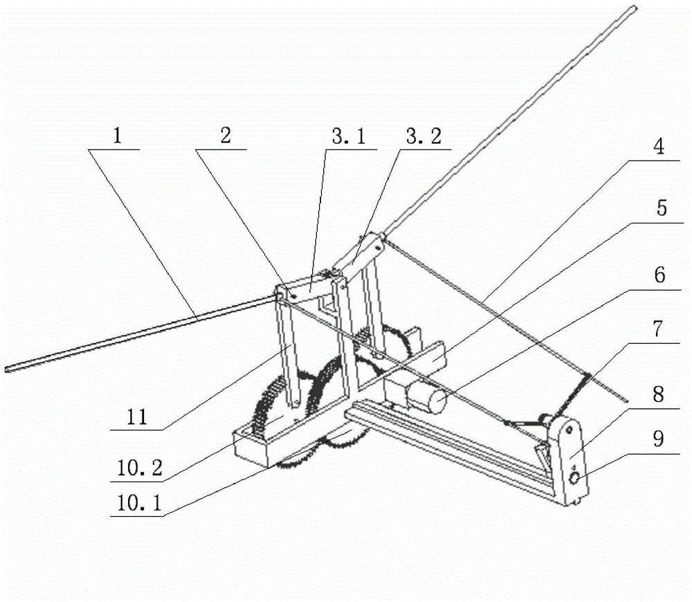
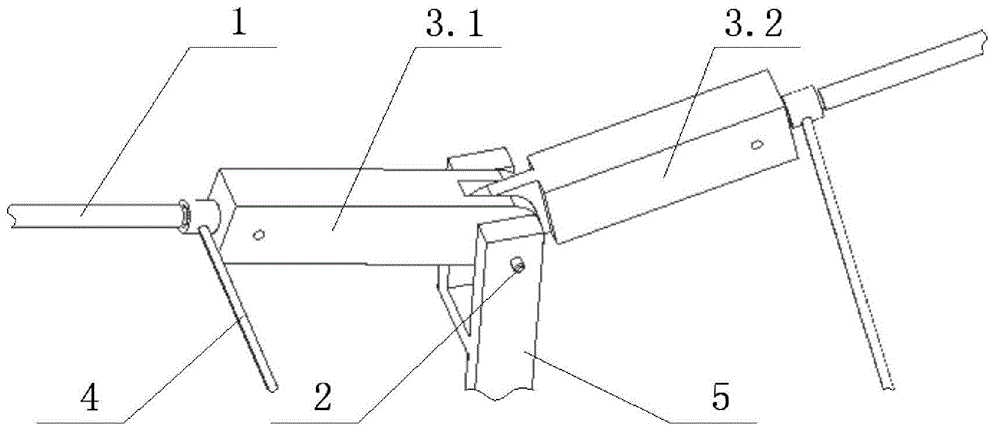
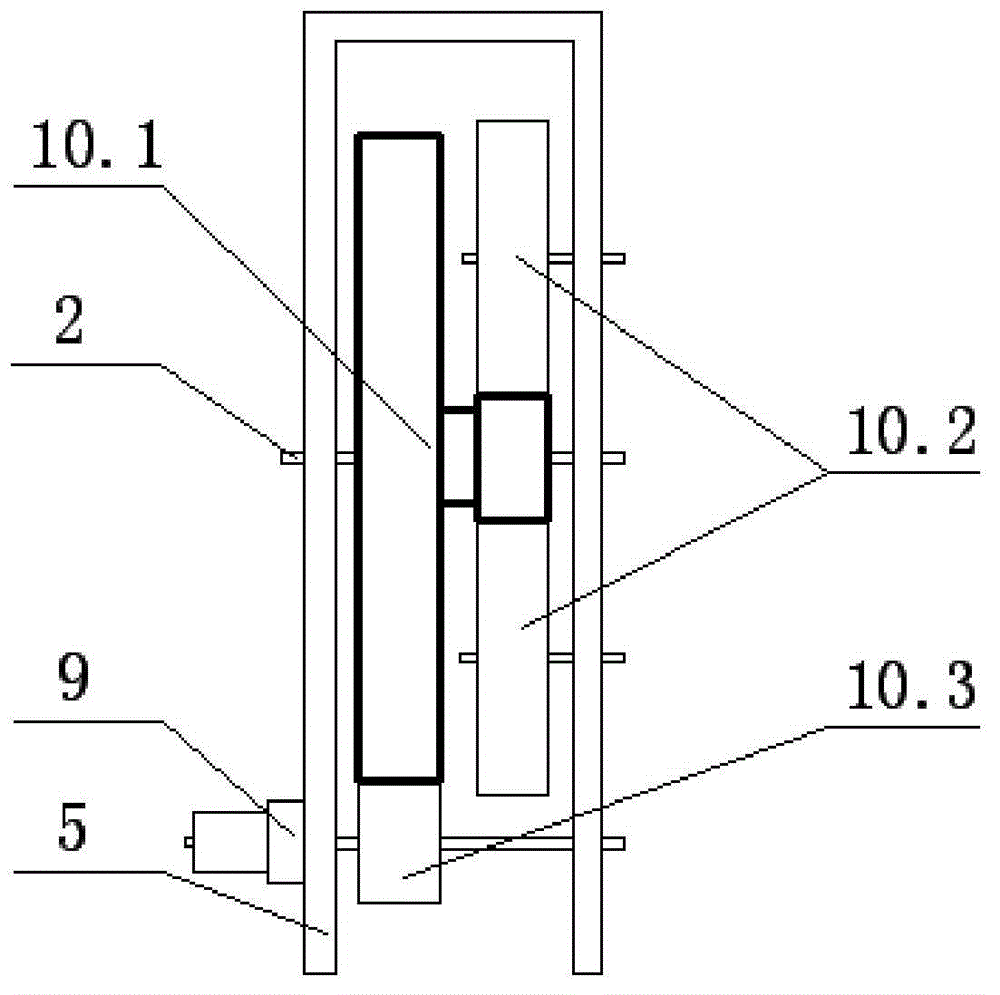
[0026] Such as figure 1 Shown, a micro-aircraft flapping wing and steering device, including flapping wing device and steering device. Flapping wing device comprises flapping wing rocking bar 1, cylindrical pin 2, left wing connecting plate 3.1, right wing connecting plate 3.2, mounting frame 5, drive motor 6, connecting rod 11, double-layer gear 10.1, bull gear 10.2 and pinion 10.3. The flapping wing rocker 1 is a cylindrical long rod, and one end connected to the connecting plate is slightly thinner, so that it can be easily inserted into the corresponding connecting plate hole. The flapping wing rocker 1 is used to fix the wings and drive the wings to flutter. There are small holes in the center of one end connecting the connecting plate with the thin end of the flapping rocker 1 and at the connecting point between the outer side and the co...


PUM


Abstract

The invention discloses a flapping wing and turning device of a micro aerial vehicle. The flapping wing and turning device comprises a flapping wing rocking rod, a round pin, a connecting plate, a driving motor, a connecting rod, an installing frame, a gear, a turning rod, a tail wing supporting plate, a turning motor, a swinging arm, a rotating component and a swinging frame, wherein the driving motor drives a first-grade pinion to rotate, and the first-grade pinion drives a double-layer gear to rotate, and the double-layer gear drives second-grade gears at two sides to rotate, and the second-grade gear drives the connecting rod to move, and the connecting rod drives a left wing connecting plate, a right wing connecting plate and a flapping wing rocking rod to swing up and down so as to achieve the flapping of the wing. The turning motor drives a rocking frame to rock, the rotating component in the rocking frame drives the rocking arm to rotate around the round pin, so that the angles of two turning rods are deviated, and as a result, the aerial vehicle can be turned. According to the flapping wing and turning device, the flapping wing and the turning device are integrated, so that the benefit is brought to the microminiaturization of the flapping wing aerial vehicle; and meanwhile, the flapping wing and turning device has the characteristics of being simple in structure, flexible and small.

Description

technical field [0001] The invention belongs to the field of micro-aircraft design, and relates to a flapping wing and steering device of a micro-aircraft. Background technique [0002] Although flying creatures such as insects and birds in nature have different shapes and structures of wings, they all adopt the flapping flight mode. The research results of bionics and aerodynamics show that when the wingspan is less than 15cm, flapping-wing flight has more advantages than fixed-wing and rotary-wing flying. Compared with fixed-wing and rotary-wing flying, flapping-wing flight has the characteristics of taking off in situ or in a small field, good flight maneuverability and certain hovering performance in the air, and less energy consumption for long-distance flight. The bionic flapping wing aircraft is a new type of aircraft designed and manufactured based on the principle of bionics by imitating the flight of birds and insects. The flapping-wing aircraft has a wide range ...

Claims


Application Information

Patent Timeline
Patent Type & Authority Applications(China)
IPC IPC(8): B64C33/00B64C33/02
Inventor 张志胜尹东富金晓怡史金飞
Owner SOUTHEAST UNIV
Why Eureka
Try Eureka