Combined fire hole
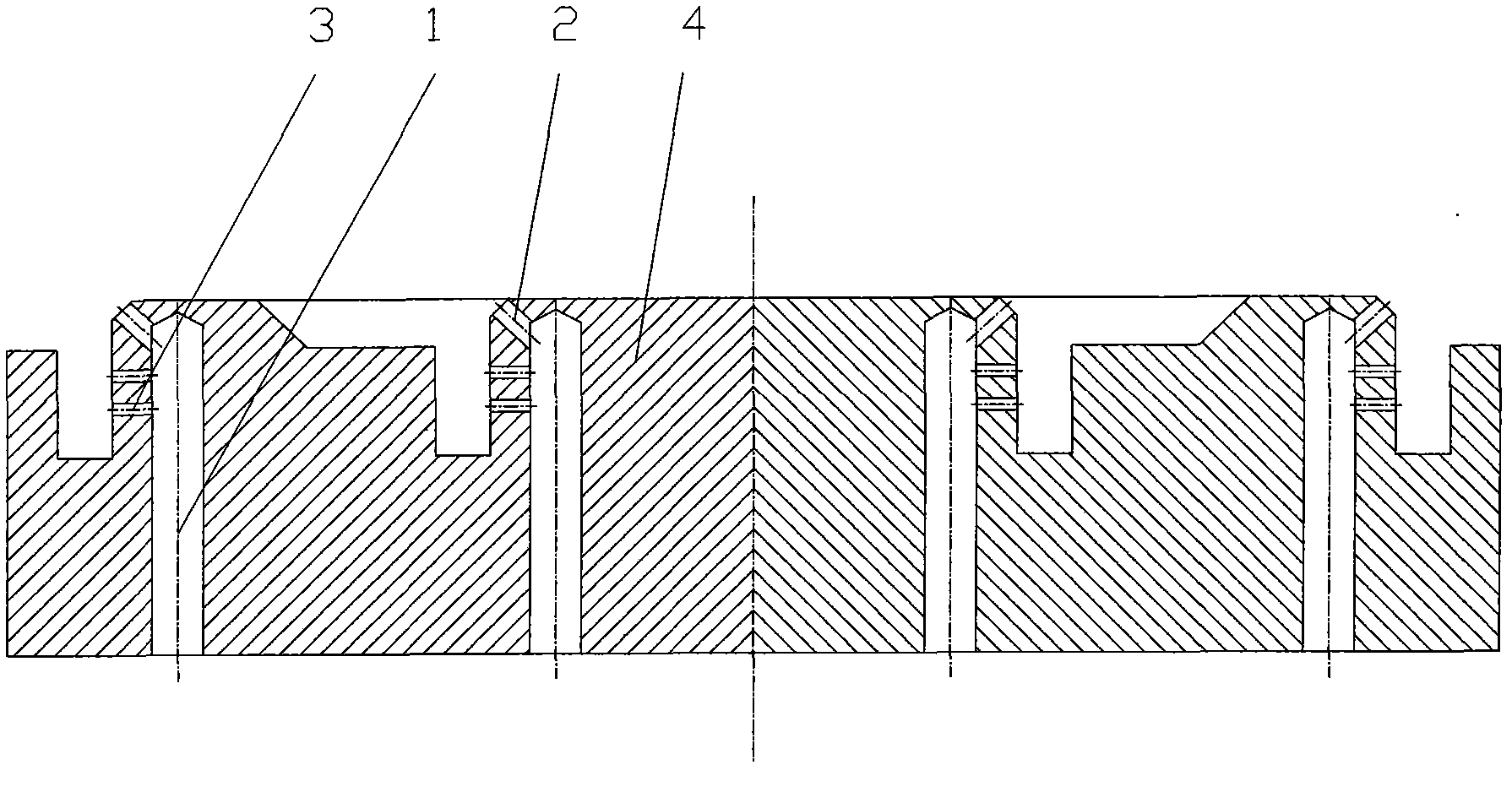
A combined fire hole technology, applied to gas fuel burners, combustion methods, combustion types, etc., can solve the problem of destroying the independent characteristics of circular fire holes, making circular fire holes unusable, and circular fire holes unusable, etc. problems, to meet the design requirements and use requirements
- Summary
- Abstract
- Description
- Claims
- Application Information
AI Technical Summary
Problems solved by technology
Method used
Image
Examples
Embodiment 1
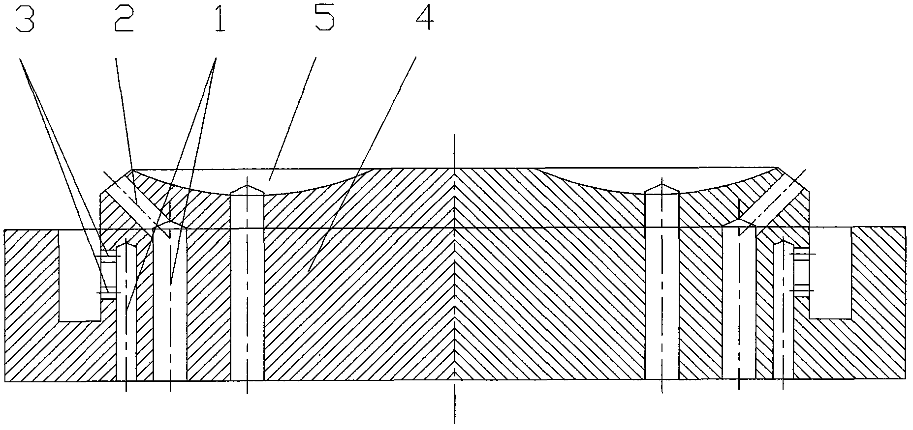
[0015] Embodiment 1: the combined use of combined fire hole and slit type combined fire hole, for directional outflow hole and stable flame outflow hole, gas introduction hole is set separately, as figure 2 As shown, the gas introduction hole 1, the directional outflow hole 2, the stable flame outflow hole 3, the combustion plate 4, the slit combined fire hole 5, the gas introduction hole 1 is a non-penetrating circular air channel processed longitudinally on the combustion plate 4 , the upper end is in a closed state, and the lower end opening communicates with the premixed gas chamber; the directional outflow hole 2 is a circular air channel that can be processed in any direction and at any inclination angle, intersects and communicates with the gas introduction hole 1, and its inlet is open to the gas introduction In the inside of the hole 1, the outlet is open in the combustion reaction zone; the stable flame outflow hole 3 is a circular or slit-shaped gas hole processed h...
Embodiment 2
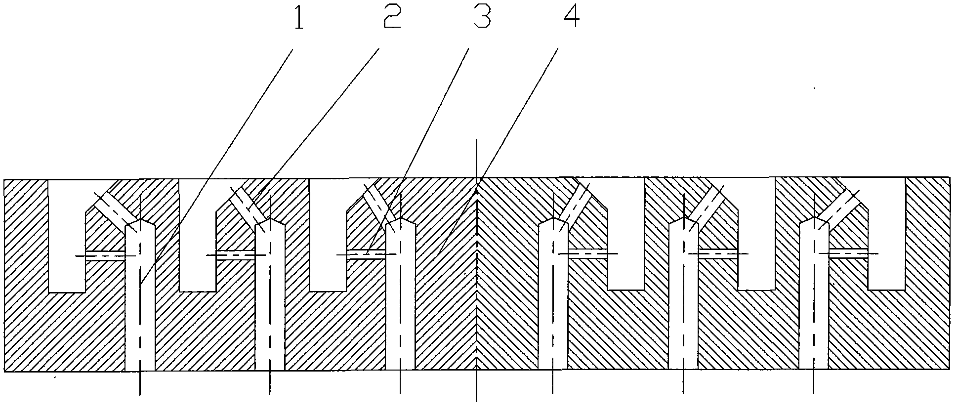
[0016] Embodiment 2: The inclination angles of the directional outflow holes are different, such as image 3 As shown, the gas introduction hole 1, the directional outflow hole 2, the stable flame outflow hole 3, the combustion plate 4, the slit combined fire hole 5, the gas introduction hole 1 is a non-penetrating circular air channel processed longitudinally on the combustion plate 4 , the upper end is in a closed state, and the lower end opening communicates with the premixed gas chamber; the directional outflow hole 2 is a circular air channel that can be processed in any direction and at any inclination angle, intersects and communicates with the gas introduction hole 1, and its inlet is open to the gas introduction In the inside of the hole 1, the outlet is open in the combustion reaction zone; the stable flame outflow hole 3 is a circular or slit-shaped gas hole processed horizontally on the side wall of the gas introduction hole 1, located below the directional outflow ...
Embodiment 3
[0017] Embodiment 3: The orientation of the directional outflow hole is different, such as Figure 4 As shown, the gas introduction hole 1, the directional outflow hole 2, the stable flame outflow hole 3, the combustion plate 4, the slit combined fire hole 5, the gas introduction hole 1 is a non-penetrating circular air channel processed longitudinally on the combustion plate 4 , the upper end is in a closed state, and the lower end opening communicates with the premixed gas chamber; the directional outflow hole 2 is a circular air channel that can be processed in any direction and at any inclination angle, intersects and communicates with the gas introduction hole 1, and its inlet is open to the gas introduction In the inside of the hole 1, the outlet is open in the combustion reaction zone; the stable flame outflow hole 3 is a circular or slit-shaped gas hole processed horizontally on the side wall of the gas introduction hole 1, located below the directional outflow hole 2, ...
PUM
 Abstract
Description
Claims
Application Information
 - R&D
- Intellectual Property
- Life Sciences
- Materials
- Tech Scout
- Unparalleled Data Quality
- Higher Quality Content
- 60% Fewer Hallucinations
Browse by: Latest US Patents, China's latest patents, Technical Efficacy Thesaurus, Application Domain, Technology Topic, Popular Technical Reports.
© 2025 PatSnap. All rights reserved.Legal|Privacy policy|Modern Slavery Act Transparency Statement|Sitemap|About US| Contact US: help@patsnap.com


