Dehumidifying machine

A dehumidifier and float technology, applied in the field of refrigeration and air conditioning, can solve the problems of foam debris filling the water tank, foam damage, foam falling off, etc., and achieve the effects of improving service life, saving costs, and reducing potential safety hazards.

Active Publication Date: 2015-04-08
GREE ELECTRIC APPLIANCES INC
View PDF5 Cites 0 Cited by
  • Summary
  • Abstract
  • Description
  • Claims
  • Application Information

AI Technical Summary

Problems solved by technology

However, due to the phenomenon of foam shedding and foam damage in this kind of float, it is easy to fill the water tank with foam debris, which brings potential safety hazards

Method used


Image

  • Dehumidifying machine
  • Dehumidifying machine
  • Dehumidifying machine

Examples


Embodiment Construction

[0029] Hereinafter, the present invention will be described in detail with reference to the drawings and examples. It should be noted that, in the case of no conflict, the embodiments in the present application and the features in the embodiments can be combined with each other.

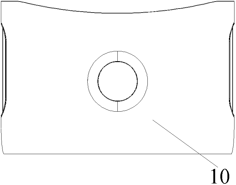
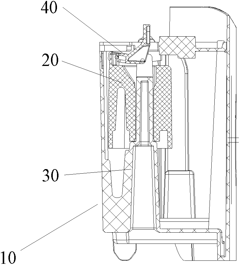
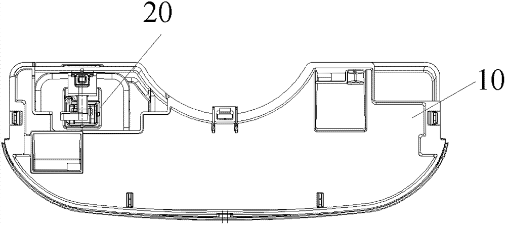
[0030] Such as Figure 1 to Figure 11 As shown, according to the embodiment of the present invention, the dehumidifier includes a water tank 10, a guide device is arranged in the water tank 10 along the vertical direction, and a float 20 that can float up and down along the guide device is arranged on the guide device. The float 20 is located on the top of the water tank 10 and includes an inner ring wall 21 , an outer ring wall 22 and a bottom wall 23 . The bottom wall 23 is located at one end of the float 20 and connects the inner ring wall 21 and the outer ring wall 22 . The inner ring wall 21 , the outer ring wall 22 and the bottom wall 23 are surrounded together so that the float 20 forms a cav...


PUM


Abstract

The invention provides a dehumidifying machine, comprising a water case (10), a floater (20), a guiding device, a linkage device and a control device, wherein the floater (20) comprises an inner annular wall (21), an outer annular wall (22) and a bottom wall (23); a cavity body opened downwards is surrounded by the inner annular wall (21), the outer annular wall (22) and the bottom wall (23); the guiding device is vertically arranged in the water case (10); the floater (20) is arranged on the guiding device and is floated up and down along the guiding device; the linkage device is connected with the floater (20) and moves up and down along the floater (20); and the control device is connected with the linkage device and controls the working state of the humidifying machine according to the movement of the linkage device. According to the invention, the humidifying machine can effectively avoid the problem of overmuch fragment because of fallen and damage foam and the like on the floater; the fragment is prevented from influencing the protective alarming function of the floater; the safety performance of the dehumidifying machine is improved; and the production cost of the floater is saved.

Description

technical field [0001] The invention relates to the field of refrigeration and air conditioning, in particular to a dehumidifier. Background technique [0002] Dehumidifiers, also known as dehumidifiers, can generally be divided into two categories: household dehumidifiers and industrial dehumidifiers, and belong to a small member of the refrigeration and air-conditioning family. Usually, a dehumidifier is composed of a compressor, a heat exchanger, a fan, a water tank, a casing, and a controller. The moisture condenses into water droplets, and the humid air becomes dry air and is discharged outside the machine. This cycle reduces the indoor humidity. [0003] After the moisture in the humid air condenses into water droplets, it gathers in the water container of the dehumidifier. With the increase of the water volume in the water container, when the water level rises to a certain height, the water body in the water container needs to be cleaned. Prevent the water body from...

Claims


Application Information

Patent Timeline
Patent Type & Authority Patents(China)
IPC IPC(8): F24F11/02
Inventor 黄晓清黄辉
Owner GREE ELECTRIC APPLIANCES INC
Why Eureka
Try Eureka