Honing reamer

A technology of honing reamer and honing reaming, which is applied in reamers, honing tools, metal processing equipment, etc., can solve the problems of affecting the continuity of precision machining process, affecting the service life of honing reamer, and adversely affecting the long-term use of tools, and achieves economical efficiency. The effect of eliminating frequent twisting and contact wear, prolonging service life and avoiding wear

Active Publication Date: 2021-01-29
浙大宁波理工学院
View PDF15 Cites 1 Cited by
  • Summary
  • Abstract
  • Description
  • Claims
  • Application Information

AI Technical Summary

Problems solved by technology

[0003] However, the existing technology for adjusting the axial position of the mandrel, even if the structure of its axial movement is basically a male and female thread connected to the mandrel at the top of the cutter bar, this adjustment structure mainly has three disadvantages in the actual adjustment operation: one is the need for It can only be adjusted when the machine stops working, which affects the continuity of the precision machining process
Second, the adjustment of the mandrel is manually adjusted, which is difficult to guarantee the machining accuracy
The third is that the female thread, that is, the frequent twisting of the nut is easy to wear the male thread of the mandrel, which is not conducive to the long-term use of the tool, that is, it affects the service life of the honing reamer

Method used


Image

  • Honing reamer
  • Honing reamer
  • Honing reamer

Examples


Embodiment Construction

[0025] The specific embodiments of the present invention will be further described below in conjunction with the accompanying drawings. What needs to be declared here is that the descriptions of these specific implementations are used to help understand the present invention, but are not intended to limit the present invention. In addition, the technical features involved in the various specific embodiments of the present invention described below may be combined with each other as long as they do not constitute conflicts with each other.

[0026] Such as figure 1 , figure 2 , image 3 , Figure 4 , Figure 5 , Image 6 , Figure 7 Shown:

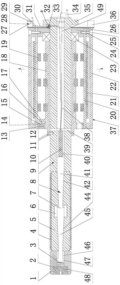
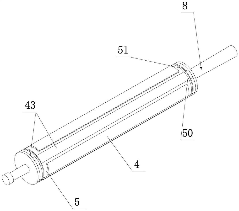
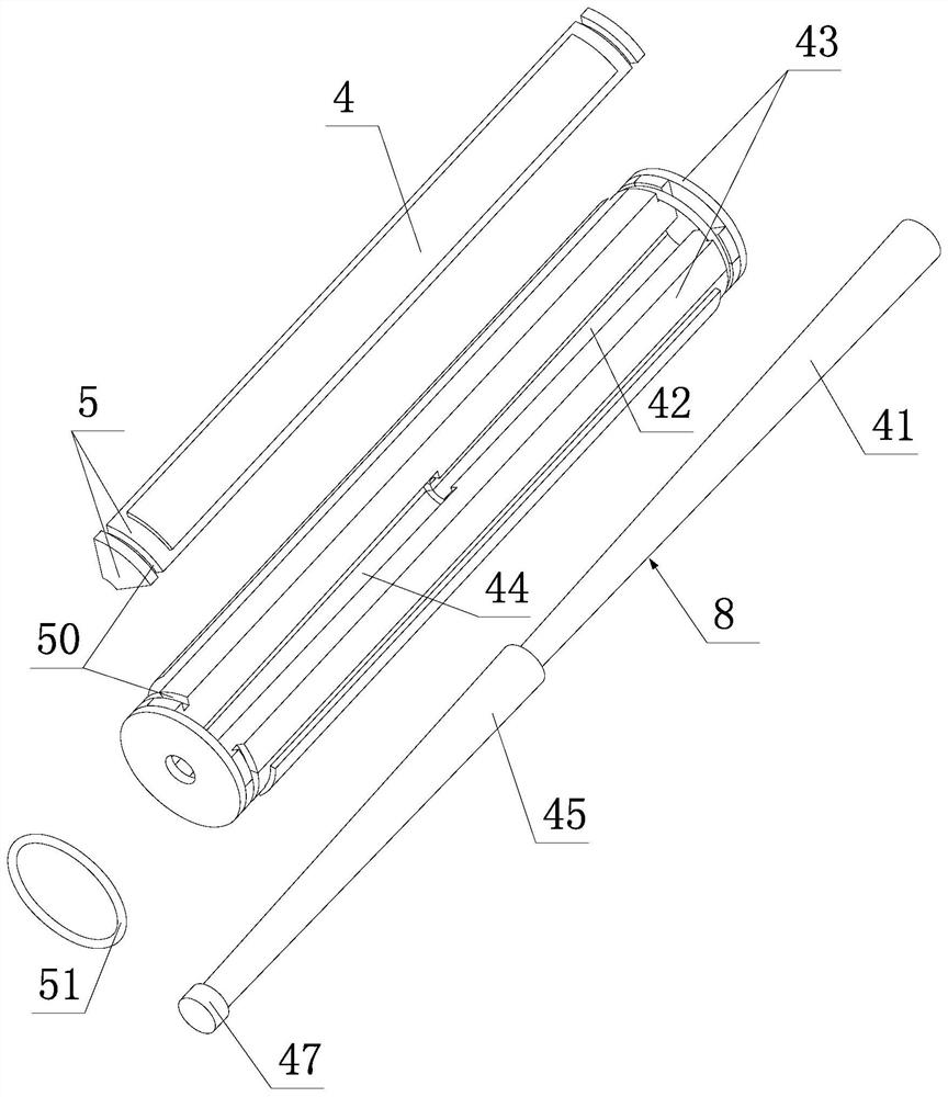
[0027] The honing reamer of the present invention comprises a circular cutter bar body 9 and a circular honing reamer base 43 which are connected end to end in the axial direction. The honing base 43 is provided with a plurality of honing bars 4 for grinding along the circumference, and the outer surface of the honing bars 4 can be...


PUM


Abstract

The invention discloses a honing reamer which comprises a circular cutter bar body and a circular frame type honing and reaming base, the circular cutter bar body is axially connected end to end, thehoning and reaming base is provided with a honing and reaming strip, one end of the cutter bar body is provided with a flange plate connected with a machine tool, and the honing and reaming base and the cutter bar body are provided with structures enabling the honing and reaming strip to automatically expand or retract in the radial direction; a piezoelectric energy harvester generating power through vibration is arranged on the cutter bar body, a piezoelectric stack capable of axially extending after being electrified is fixed in a first center hole in the cutter bar body, and the outer end of the piezoelectric stack is fixed with one end of a dabber which is used for axially moving and enabling the honing and reaming strip to radially expand or radially retract; a displacement sensor isarranged on the piezoelectric stack; and the piezoelectric energy harvester is electrically connected with the piezoelectric stack through a control circuit and a wire arranged in the cutter bar body,and the displacement sensor is electrically connected with the control circuit. According to the honing reamer, the radial position of the honing and reaming strip in the honing reamer can be automatically adjusted and compensated in the machining process, so that the grinding part of the honing and reaming strip is always kept in a grinding state, and the machining precision can be guaranteed.

Description

technical field [0001] The invention relates to the technical field of precision machining tools, in particular to a honing reamer. Background technique [0002] The honing reamer is widely used in the field of precision machining technology. Since the outer surface of the honing reamer can be coated with a layer of diamond abrasive, it can precisely process high-hardness materials. The reamer honing bar of the existing honing reamer is generally composed of a tool bar body and a mandrel. The mandrel has a certain taper or a tapered surface. By adjusting the axial position of the mandrel, the tool bar body expands, and the tool bar body The diamond abrasive on the surface continuously grinds the hole wall, so that the diameter of the processed hole is continuously enlarged, and the purpose of precision grinding of the hole to be processed is achieved. [0003] However, the prior art adjusts the axial position of the mandrel, even if the structure of its axial movement is ba...

Claims


Application Information

Patent Timeline
IPC IPC(8): B23D77/00B23D77/14B24B33/08
CPCB23D77/00B23D77/14B24B33/08
Inventor 华顺明张宇许少锋刘立君王义强
Owner 浙大宁波理工学院
Why Eureka
Try Eureka