Reverse-impact forced-power-failure type electromagnetic switch

A technology of forced power-off and electromagnetic switch, applied in electromagnetic relays, electromagnetic relay details, circuits, etc., can solve the problem of heat aging of battery +30 terminal wiring harness, damage to engine commutator and armature, and damage to battery feed and other problems, to avoid the adhesion of static and dynamic contacts, reduce the failure rate, and improve the profit margin.

Active Publication Date: 2013-01-16
马勒电驱动(太仓)有限公司
View PDF4 Cites 5 Cited by
  • Summary
  • Abstract
  • Description
  • Claims
  • Application Information

AI Technical Summary

Problems solved by technology

Moreover, the sticking of the main contact of the switch will lead to other faults of the starter, for example: 1. Due to the sticking of the main contact, the battery supplies power to the starter for a long time, and the driving gear is reversed by the flywheel ring gear during the normal operation of the engine. After a long time, the engine commutator and armature will be damaged, and the one-way device will also be damaged
2. Potential failure leading to damage to the battery feed
4. If there is a short circuit inside the starter due to damaged parts, the wiring harness at terminal +30 of the battery may also become hot and aging
[0006] The electromagnetic switches currently used are basically the above-mentioned split or integral structures, but both types of electromagnetic switches have contact adhesion, which cannot avoid failures. Therefore, switch contact adhesion is a difficult problem to be solved.

Method used


Image

  • Reverse-impact forced-power-failure type electromagnetic switch
  • Reverse-impact forced-power-failure type electromagnetic switch
  • Reverse-impact forced-power-failure type electromagnetic switch

Examples


Embodiment Construction

[0028] In order to make the object, technical solution and advantages of the present invention clearer, the present invention will be further described in detail below in conjunction with the accompanying drawings and embodiments. It should be understood that the specific embodiments described here are only used to explain the present invention, not to limit the present invention.

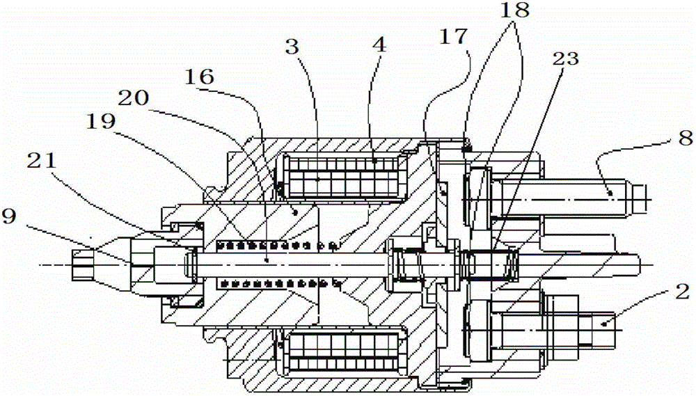
[0029] image 3 It is a schematic diagram of the electromagnetic switch of the present invention, as shown in the figure: a kind of anti-impact forced power-off electromagnetic switch, comprising a moving iron core 16, a suction coil 3 and a holding coil 4 arranged outside the moving iron core 16 successively, connected Rod 20, hook 9, movable contact 17 and static contact 18 that can be connected with the movable contact, the center of the moving iron core 16 is provided with a step-shaped inner hole that is thin in the middle and thick at both ends, and the hook 9 is connected with the moving iro...


PUM


Abstract

The invention discloses a reverse-impact forced-power-failure type electromagnetic switch. The reverse-impact forced-power-failure type electromagnetic switch comprises a movable iron core, a sucking and pulling coil and a holding coil, a connecting rod, a hook, a movable contact and a static contact, wherein the sucking and pulling coil and the holding coil are arranged outside the movable iron core in sequence; the static contact can be connected with the movable contact; a stepped inner hole which is thin at the middle part and thick at two ends is arranged at the middle part of the movable iron core; the hook is connected with the movable iron core; the tail end of the hook is provided with a groove communicated with the inner hole of the movable iron core; the tail end of the connecting rod is arranged in the groove of the hook, and a rod body extends out of the inner hole of the movable iron core; and the tail end of the connecting rod is provided with a washer, and the initial end of the connecting rod is connected with the movable contact. The reverse-impact forced-power-failure type electromagnetic switch disclosed by the invention has the advantages that the occurrence of faults of adhesion of the electromagnetic switch can be avoided, further the fault rate of a whole starter is reduced and a zero-kilometer PPM value and a after-sale PPM value of an engine company are reduced.

Description

technical field [0001] The invention relates to the technical field of automobile electrical equipment, in particular to an anti-impact forced power-off electromagnetic switch. Background technique [0002] At present, in the zero-kilometer and after-sales failure rate statistics of automobile engine parts, the proportion of starters is always at the top. Among these failures, the failure proportion of electromagnetic switches is particularly prominent, becoming one of the main failure modes. In the electromagnetic switch failure mode, the main contact adhesion of the switch is also a common phenomenon. In addition, the adhesion of the main contact of the switch will lead to other failures of the starter, for example: 1. Due to the adhesion of the main contact, the battery supplies power to the starter for a long time, and the driving gear is reversed by the flywheel ring gear during the normal operation of the engine. After a long time, the engine commutator and armature w...

Claims


Application Information

Patent Timeline
Patent Type & Authority Applications(China)
IPC IPC(8): H01H50/16H01H50/54
Inventor 王立军金雯芬苏琦烨张敏
Owner 马勒电驱动(太仓)有限公司
Why Eureka
Try Eureka