Anti-shake method and device for shooting
An anti-shake and electronic anti-shake technology, applied in projection devices, printing devices, televisions, etc., can solve the problems of low image definition, inability to obtain anti-shake effects, and inaccurate image position changes, and achieve clear shooting images, Best anti-shake effect, accurate effect of position change parameters
- Summary
- Abstract
- Description
- Claims
- Application Information
AI Technical Summary
Problems solved by technology
Method used
Image

Examples
Embodiment 1
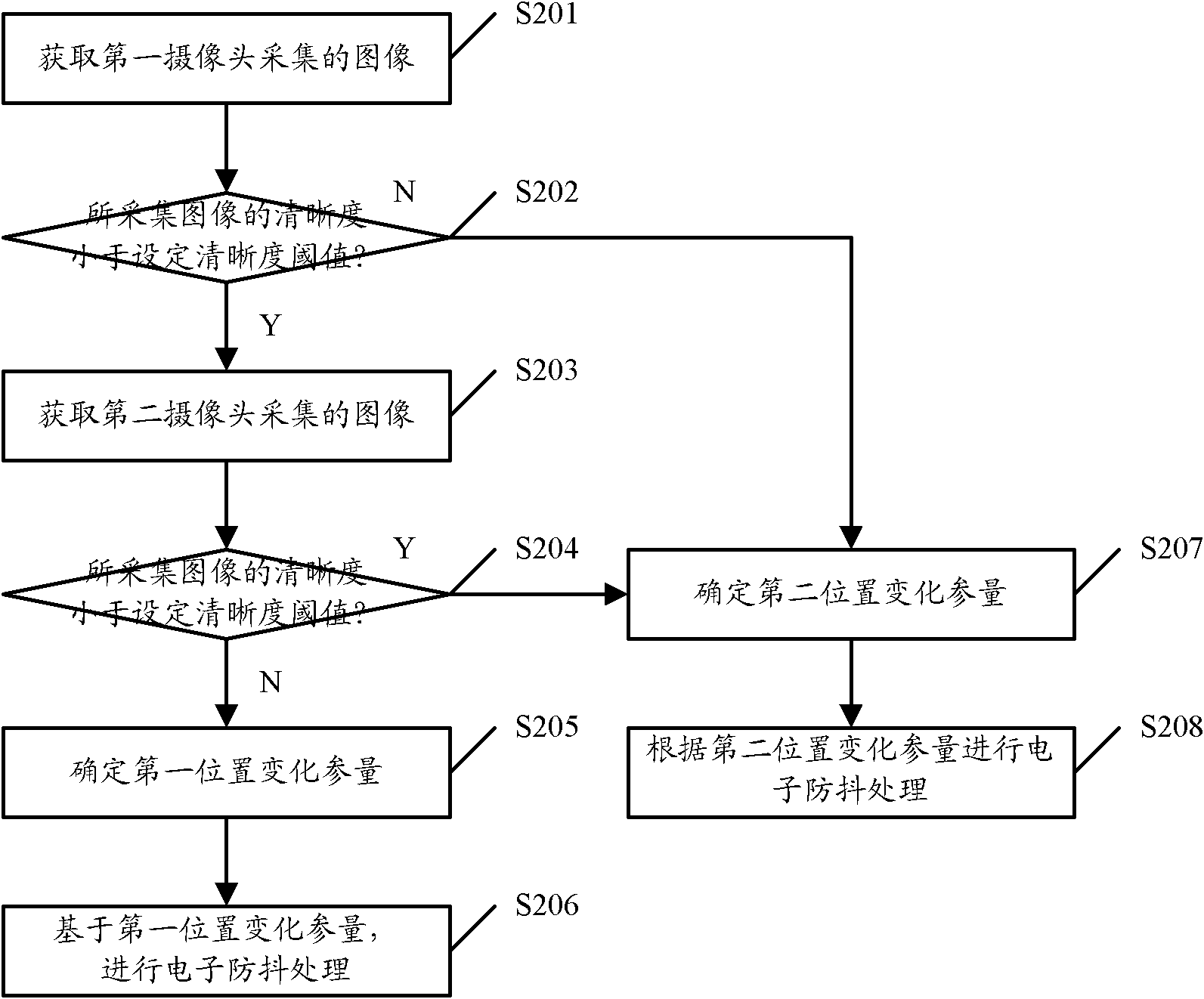
[0032] figure 2 Shown is a flow chart of the shooting anti-shake method provided in Embodiment 1 of the present invention, which specifically includes the following processing steps:
[0033] Step S201. After the first camera used for the current shooting is turned on, the first camera will collect images in real time and cache them. The shooting device to which the first camera belongs acquires the images captured by the first camera, specifically, it may periodically acquire the latest images currently captured, and the acquisition period may be determined according to the attributes, use experience and actual needs of the cameras.
[0034] Step S202 , judging whether the resolution of the image captured by the first camera is less than the set resolution threshold, if yes, proceed to step S203 , otherwise, proceed to step S207 .
[0035] Due to the influence of light in the shooting environment where the current shooting device is located, the clarity of the image capture...
Embodiment 2
[0065] Figure 5 Shown is a flow chart of the shooting anti-shake method provided in Embodiment 2 of the present invention, which specifically includes the following processing steps:
[0066] Step S501, after the first camera used for the current shooting is turned on, the first camera will collect images in real time and cache them. The shooting device to which the first camera belongs acquires the images captured by the first camera, specifically, it may periodically acquire the latest images currently captured, and the acquisition period may be determined according to the attributes, use experience and actual needs of the cameras.
[0067] Step S502 , when the first camera used for the current shooting is turned on, the second camera is turned on at the same time, and the second camera collects images in real time and caches them. The shooting device then acquires the image captured by the second camera, specifically, it may periodically acquire the latest image currently...
Embodiment 3
[0079] Based on the same inventive concept, according to the anti-shake method provided by the above-mentioned embodiments of the present invention, correspondingly, Embodiment 3 of the present invention also provides an anti-shake device for shooting, which can be installed on In the shooting equipment of the two cameras, the schematic diagram of its structure is as follows Image 6 shown, including:
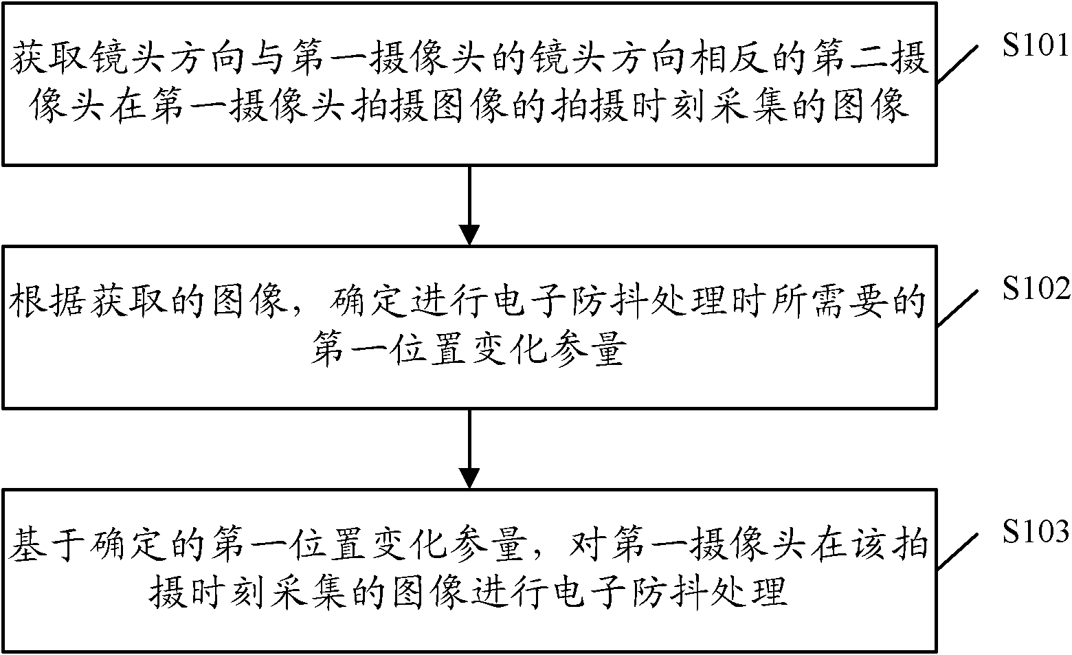
[0080] An acquisition unit 601, configured to acquire an image captured by a second camera whose lens direction is opposite to that of the first camera at the time when the first camera captures the image;
[0081] A parameter determining unit 602, configured to determine a first position change parameter required for electronic anti-shake processing according to the acquired image;
[0082] The processing unit 603 is configured to perform electronic anti-shake processing on the image captured by the first camera at the shooting moment based on the determined first position ch...
PUM
 Abstract
Description
Claims
Application Information
 - R&D
- Intellectual Property
- Life Sciences
- Materials
- Tech Scout
- Unparalleled Data Quality
- Higher Quality Content
- 60% Fewer Hallucinations
Browse by: Latest US Patents, China's latest patents, Technical Efficacy Thesaurus, Application Domain, Technology Topic, Popular Technical Reports.
© 2025 PatSnap. All rights reserved.Legal|Privacy policy|Modern Slavery Act Transparency Statement|Sitemap|About US| Contact US: help@patsnap.com