Supporting device and supporting method for machining propeller blade

A support device and propeller technology, which is applied in positioning devices, metal processing equipment, metal processing machinery parts, etc., can solve the problems of reducing processing efficiency, propeller deformation, affecting processing accuracy, etc., and achieves improved support effect, increased rigidity, and simple structure Effect

Inactive Publication Date: 2013-01-23
JIANGSU UNIV OF SCI & TECH
View PDF5 Cites 19 Cited by
  • Summary
  • Abstract
  • Description
  • Claims
  • Application Information

AI Technical Summary

Benefits of technology

This technology helps prevent damage or deformation caused when rotating wings are used at high altitudes such as those found near space stations. It uses an underwater suckup cups attached to supports placed over these wings to help them stay stable even if they become too shaky due to factors like wind pressure. By absorbing and supporting certain parts of the blade's movement with this system, it improves its strength while also allowing precise placement within specific areas around the wing. Additionally, there may have been other technical features related thereto - including analysis tools to determine the location of the supported part(s) (the hub), and various sensors to monitor how well the braking action works properly. Overall, this technology provides effective solutions for maintaining flight control stability without causing any issues.

Problems solved by technology

This patented technical problem addressed in this patents relates to improving the process of cutting high-strength integrated propellers while ensuring that they maintain their desired properties such as strength without being affected due to imperfections like bending stress caused when supporting them on an external frame.

Method used


Image

  • Supporting device and supporting method for machining propeller blade
  • Supporting device and supporting method for machining propeller blade
  • Supporting device and supporting method for machining propeller blade

Examples


Embodiment Construction

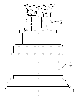
[0025] like figure 1 As shown, the supporting device for processing propeller blades of the present invention is composed of a vacuum chuck assembly 5 and a base 4, the vacuum chuck assembly 5 is located on the base 4, and the base 4 and the vacuum chuck assembly 5 are connected by bolts.

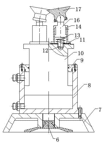
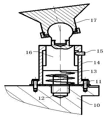
[0026] like figure 2 As shown, the base 4 includes a bottom vacuum suction cup 6, a chassis 7, a hydraulic cylinder 8, a hydraulic cylinder cover 9 and a piston rod 10, and the bottom vacuum suction cup 6 is installed at the bottom middle of the chassis 7, and is used between the chassis 7 and the bottom vacuum suction cup 6. threaded connection. A hydraulic cylinder 8 is installed in the middle of the top of the chassis 7, and the sampling bolts between the hydraulic cylinder 8 and the base 7 are connected. The hydraulic cylinder cover 9 is connected to the top surface of the hydraulic cylinder 8 by threads. The bottom end of the piston rod 10 extends into the hydraulic cylinder 8, and...


PUM


Abstract

The invention discloses a supporting device and a supporting method for machining a propeller blade. The supporting device consists of a base and a vacuum sucker component positioned on the base, wherein the base comprises a bottom vacuum sucker, a chassis, a hydraulic cylinder and a piston rod, the middle of the bottom of the chassis is connected with the bottom vacuum sucker, the middle of the top of the chassis is provided with the hydraulic cylinder, the bottom end of the piston rod extends into the hydraulic cylinder, and the vacuum sucker component comprises a limiting switch, a spring, a support, a mandril, a positioning screw and a top sucker. The propeller blade is analyzed and calculated to determine the area in which the supporting device is positioned. For the propeller blade with the diameter less than 4 meters, supporting points of the supporting device are distributed at five positions of the propeller blade; and for the propeller blade with the diameter more than 4 meters, the supporting points of the supporting device are distributed at seven positions of the propeller blade. According to the invention, supporting can be quickly completed, and the stiffness of the supporting device and a supporting effect of the propeller blade can be improved.

Description


Claims


Application Information

Patent Timeline
Owner JIANGSU UNIV OF SCI & TECH
Why Eureka
Try Eureka