Movable combination pin

A movable and pin technology, applied in the direction of connecting components, bolts, mechanical equipment, etc., can solve the problems of inconvenient disassembly and assembly, difficult to restore the original state, and large consumption.

Inactive Publication Date: 2013-01-23
CRRC QIQIHAR ROLLING CO LTD
View PDF4 Cites 7 Cited by
  • Summary
  • Abstract
  • Description
  • Claims
  • Application Information

AI Technical Summary

Problems solved by technology

The disassembly of this kind of cotter pin requires the help of tools. For the pin shaft that is often disassembled, it is very inconvenient to use cotter pins, and it is very inconvenient to use cotter pins for disassembly and assembly in narrow spaces.
In addition, the shape of the cotter pin changes after disassembly, and it is difficult to restore the original shape. In most cases, it cannot be reused, and the consumption is relatively large.

Method used


Image

  • Movable combination pin
  • Movable combination pin
  • Movable combination pin

Examples


Embodiment Construction

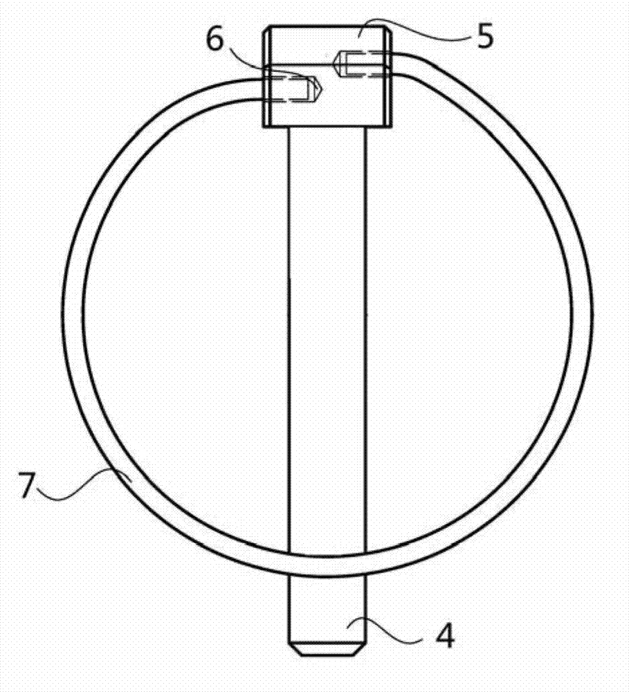
[0019] image 3 It is a schematic structural diagram of a movable combination pin provided in this embodiment, Figure 4 The schematic diagram of the use state of the active combination pin provided for this embodiment, combined with image 3 and Figure 4 As shown, the movable combination pin provided in this embodiment includes a cylindrical pin shaft 4, and one end of the pin shaft 4 is provided with a boss 5, and the boss 5 has two holes 6, and the two holes 6 are respectively located on opposite sides of the boss 5. Both sides, and the axes of the two holes 6 are not on the same straight line; the movable combination pin also includes an elastic ring 7, the elastic ring 7 is annular with an opening, and its two ends are inserted into the two holes 6 respectively. The diameter of the pin shaft 4 in the movable combination pin is preferably the diameter of a standard cotter pin. The shape of the pin shaft 4 matches the pin hole shape, if the pin hole shape is a circular ...


PUM

PropertyMeasurementUnit
Diameteraaaaaaaaaa

Abstract

The invention provides a movable combination pin which comprises a columnar pin shaft. One end of the pin shaft is provided with a boss, the boss is provided with two holes, the holes are located at opposite two sides of the boss respectively, and axes of the two holes are not on one identical straight line; the movable combination pin further comprises an elastic ring which is in the shape of a loop with an opening, and two ends of the elastic ring are inserted into the two holes respectively. According to the movable combination pin provided by the invention, the columnar pin shaft of which one end is provided with the boss, the opposite two sides of the boss are provided with the two holes of which the axes are not on one identical straight line and the elastic ring is inserted into the two holes; as two hinge points of the elastic ring are not on one identical straight line, an elastic force is generated after the elastic ring is buckled on the pin shaft to lock, so as to realize self locking of the movable combination pin, and guarantee that the movable combination pin does not fall off when vibrating and rotating along with a locking shaft.

Description

technical field [0001] The invention relates to a mechanical structure, in particular to a movable combination pin. Background technique [0002] In mechanical positioning and transmission, the mechanism with the pin shaft as the hinge point and the shaft end positioning of the locking shaft mostly use a washer and a cylindrical cotter pin. The washer and cotter pin have become standard parts such as GB / T95 and GB / T91. figure 1 It is a structural schematic diagram of the connection between the cotter pin and the shaft end of the locking shaft in the prior art, figure 2 for figure 1 Schematic diagram of the side structure of the connection between the cotter pin and the shaft end of the locking shaft, combined with figure 1 and figure 2 shown. The cotter pin 1 passes through the pin hole of the shaft end 2, and cooperates with the washer 3. It can be seen that the cotter pin 1 is folded into a ring in the middle, and then the two ends of the ring are brought together do...

Claims


Application Information

Patent Timeline
IPC IPC(8): F16B19/02F16B21/18
Inventor 张力群于跃张宇李虎键韩晶
Owner CRRC QIQIHAR ROLLING CO LTD
Why Eureka
Try Eureka