Fault detection method and device

A fault detection and detection circuit technology, applied in the electrical field, can solve problems such as inability to adapt to load connections, and achieve the effects of easy implementation, cost saving, and simple circuit structure

Inactive Publication Date: 2013-01-23
SIEMENS AG
View PDF8 Cites 18 Cited by
  • Summary
  • Abstract
  • Description
  • Claims
  • Application Information

AI Technical Summary

Problems solved by technology

However, the so-called "non-disruptive" test method is not really non-disruptive, and it needs to cut off the load temporarily during the test, so it cannot adapt to all types of load connections.

Method used


Image

  • Fault detection method and device
  • Fault detection method and device
  • Fault detection method and device

Examples


Embodiment Construction

[0056] In order to have a clearer understanding of the technical features, purposes and effects of the present invention, the specific implementation of the present invention will now be described with reference to the accompanying drawings, in which the same reference numerals represent the same parts. In order to clearly show the interrelationships of the various components, the proportional relationship of the various components in the drawings is only schematic and does not represent the proportional relationship of the actual structure.

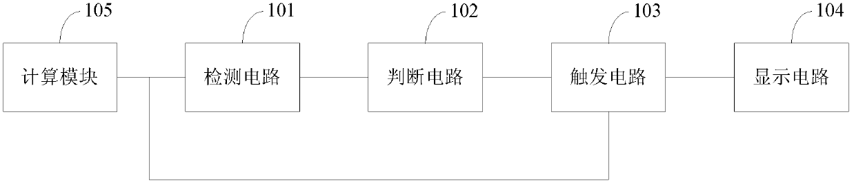
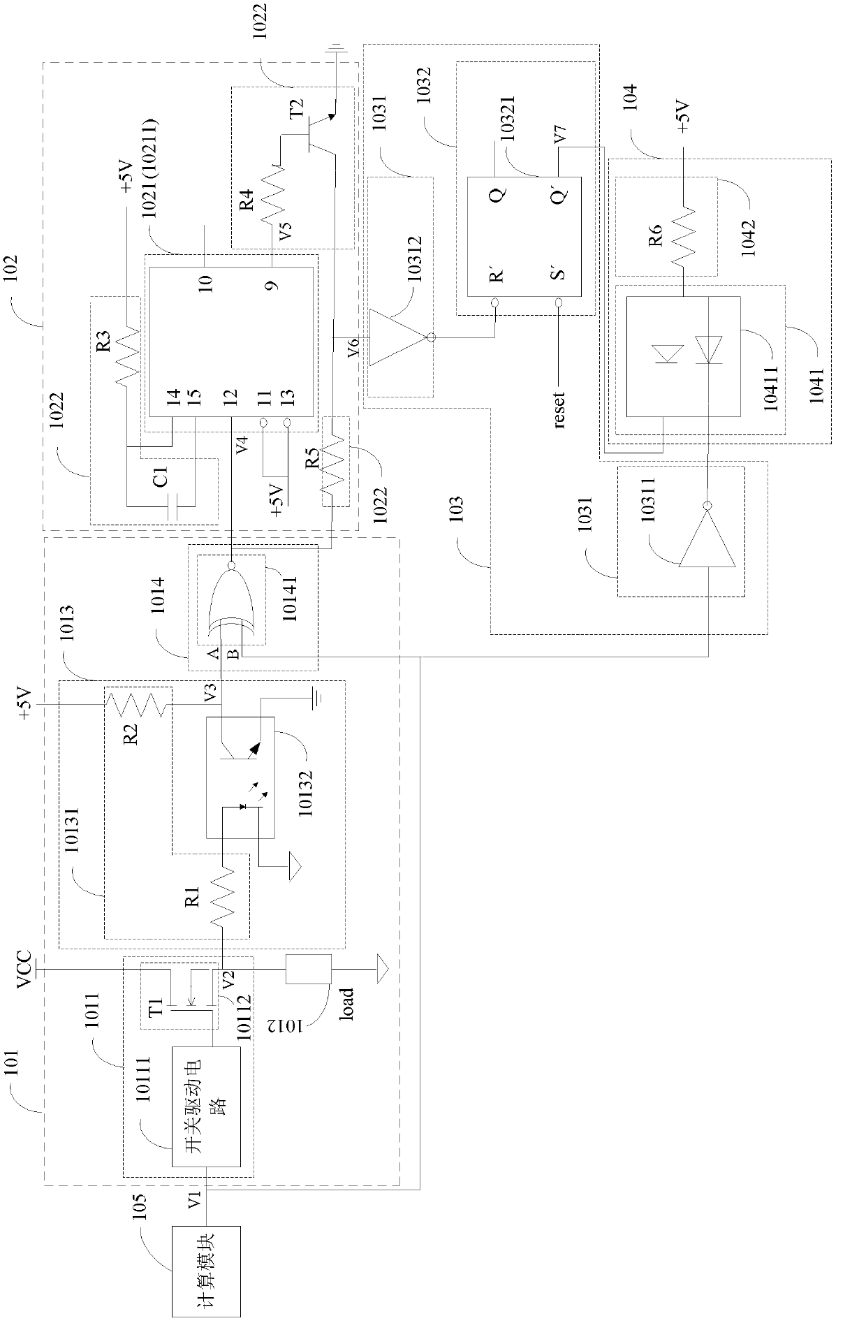
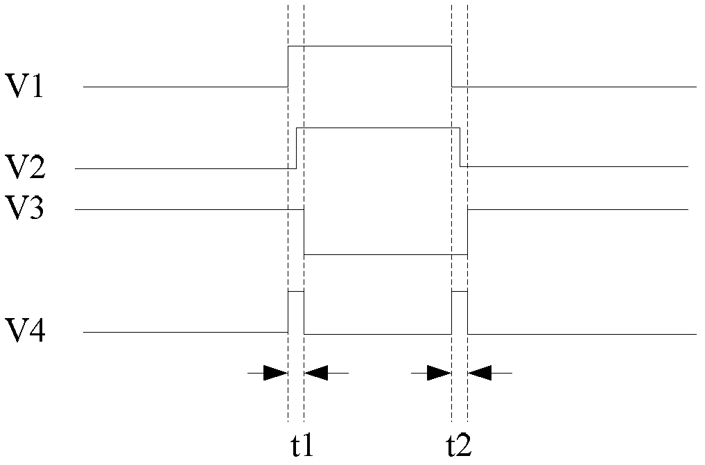
[0057] see figure 1 , the fault detection device in the embodiment of the present invention includes a detection circuit 101 , a judgment circuit 102 , a trigger circuit 103 and a display circuit 104 . The input end of detection circuit 101 is connected with the output end of device under test, for example, in the embodiment of the present invention, device under test is the digital output channel of PLC, and then the input end of detec...


PUM


Abstract

The invention discloses a fault detection device which is convenient for detecting a non-interruptible fault of a digital output channel and achieves the advantages of being simple, convenient and relatively low in cost. The fault detection device comprises a detecting circuit, a determining circuit, a triggering circuit and a displaying circuit; the detecting circuit is used for detecting the first levels of first detecting points arranged in front of a switch and a load part in a PLC (Programmable Logic Controller) system and the second levels of second detecting points arranged at back of the switch and the load part in the PLC system and correspondingly outputting relevant first pulse signals based on the variation of the first levels and the second levels; the determining circuit is used for determining whether the pulse width of the received first pulse signals is within the allowed range, if the pulse width of the received first pulse signals is not within the allowed range, outputting second pulse signals; the triggering circuit is used for triggering the displaying circuit based on the received second pulse signals; and the displaying circuit is used for responding to the received signals and displaying the detecting results. The invention also discloses a fault detection method.

Description

technical field [0001] The invention relates to the electrical field, in particular to a fault detection method and device. Background technique [0002] In the industrial control system, the switch or its driving circuit will be damaged due to external instantaneous voltage, overcurrent or other factors, and the load will also be short-circuited. Therefore, whether it is a PLC (ProgrammableLogicController, programmable logic control) device) system's fail-safe digital output channel, or the fail-safe digital output channel of the redundant PLC system used in the important process control system, or the digital output channel of the standard PLC system, its digital output channel and its control The automatic test of the connection condition of the load is very necessary. [0003] In the fail-safe digital output channel, although there are some automatic test mechanisms, additional hardware and software systems that are not related to the control process need to be added, w...

Claims


Application Information

Patent Timeline
Patent Type & Authority Applications(China)
IPC IPC(8): G01R31/327G01R31/02
CPCG05B19/058G01R31/024G01R31/318516G05B19/048
Inventor 胡喜邢建辉卓越王青岗
Owner SIEMENS AG
Why Eureka
Try Eureka