Lighting device and related projection system

A technology of light-emitting devices and polarization splitting devices, applied in lighting devices, projection devices, components of lighting devices, etc., can solve problems such as brightness reduction, high requirements for rotation stability, and distance sensitivity, so as to avoid brightness reduction Effect

Active Publication Date: 2016-01-20
APPOTRONICS CORP LTD
View PDF5 Cites 1 Cited by
  • Summary
  • Abstract
  • Description
  • Claims
  • Application Information

AI Technical Summary

Problems solved by technology

[0004] However, the disadvantage of the light-emitting device in the prior art is that: since the outgoing light of the wavelength conversion material has a full-angle exit, the outgoing light will diffuse during the propagation process, and the distance between the polarization splitting device and the surface of the outgoing light of the wavelength conversion device should be close enough , in order to receive as many outgoing light as possible from the wavelength conversion device for conversion, which has quite high requirements on the process requirements and rotational stability of the wavelength conversion device
However, in the prior art, the wavelength conversion device will rotate at a high speed driven by the driving device, and the distance between the polarization beam splitting device and the wavelength conversion device is difficult to be very close, which will cause the polarized light reflected by the polarization beam splitting device to be incident on the light circulation process. The spot on the wavelength conversion device expands, resulting in a decrease in brightness, and the degree of spot expansion is very sensitive to the distance between the polarization splitting device and the wavelength conversion device. The farther the distance is, the greater the degree of spot expansion
Therefore, in the prior art, there is a contradiction between the process requirements of the wavelength conversion device, the rotation stability and the brightness of the emitted light of the light emitting device.

Method used


Image

  • Lighting device and related projection system
  • Lighting device and related projection system
  • Lighting device and related projection system

Examples


Embodiment 1

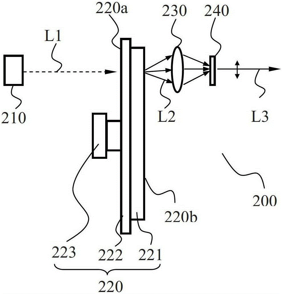
[0024] figure 2 It is a schematic structural diagram of a light-emitting device according to an embodiment of the present invention, such as figure 2 As shown, the light emitting device 200 includes an excitation light source 210 , a wavelength converting device 220 , a light collecting device 230 , and a polarization splitting device 240 .

[0025] The excitation light source 210 is used to emit excitation light L1. In this embodiment, the excitation light source 210 is specifically a blue laser light source. In other embodiments of the present invention, the excitation light source may also be an LED or phosphor light source.

[0026] The wavelength conversion device 220 includes a wavelength conversion material. The wavelength conversion material absorbs the excitation light L1 to generate the stimulated light. The wavelength conversion device 220 is used to receive the excitation light L1 and emit at least part of the stimulated emission light L2. The stimulated emissio...

Embodiment 2

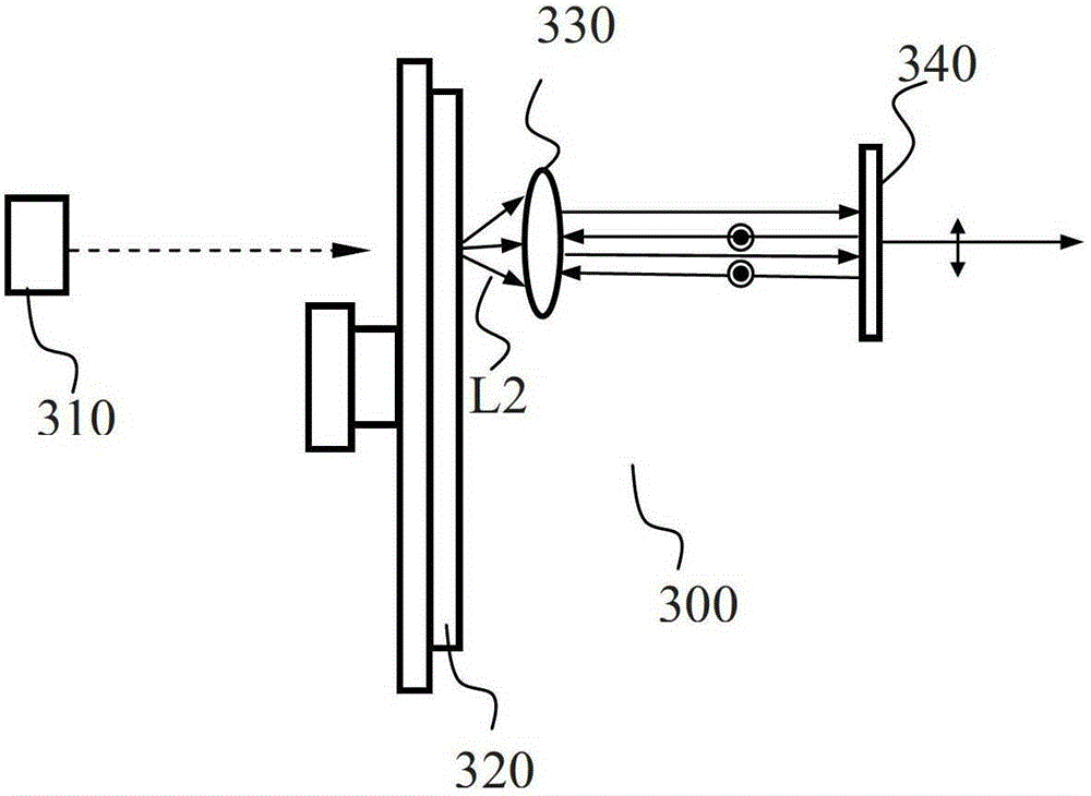
[0037] image 3 It is another structural schematic diagram of the light-emitting device according to the embodiment of the present invention, such as image 3 As shown, the light emitting device 300 includes an excitation light source 310 , a wavelength converting device 320 , a light collecting device 330 and a polarization splitting device 340 .

[0038] The light emitting device of this embodiment and figure 2 The difference between the light emitting devices shown is that the light collecting device 330 of the light emitting device 300 is a lens with a different function from the light collecting device 230 in the first embodiment, the lens 330 adjusts the outgoing light of the wavelength conversion device 320 into parallel light, and the polarization beam splitting device 340 is perpendicular to the incident direction of the parallel light, and returns the parallel light to the original path. The lens here adjusts the incident light into parallel light and emits it ver...

Embodiment 3

[0040] Figure 4a It is another structural schematic diagram of the light-emitting device according to the embodiment of the present invention, such as Figure 4a As shown, the light emitting device includes an excitation light source 410 , a wavelength converting device 420 , a light collecting device 430 and a polarization splitting device 440 . The light emitting device in this embodiment and figure 2 The light emitting device 200 shown differs in that:

[0041] 1) The substrate 422 of the wavelength conversion device 420 is provided with a reflective layer, which is located on the contact surface between the wavelength conversion layer 421 and the substrate 422, and can reflect the light emitted by the wavelength conversion layer 421 onto the reflective layer back to the first Surface 420a. The first surface 420a receives the excitation light and emits a part of the received light or a part of the mixed light of the received light and the unabsorbed excitation light. ...


PUM


Abstract

The embodiment of the invention discloses a light-emitting device and a projection device. The light-emitting device comprises an excitation light source, a wavelength conversion device, a light collection device and a polarizing beam splitting device, wherein the excitation light source is used for emitting excitation light; the wavelength conversion device is used for receiving the excitation light and emitting excited light or the excited light and unabsorbed excitation light; the light collection device is used for collecting emergent light of the wavelength conversion device and emitting the emergent light from a light path which is separated from a light path of the excitation light; the polarizing beam splitting device is used for receiving the emergent light of the light collection device, transmitting light in a first polarization state and reflecting light in a second polarization state back to the light collection device; the light collection device can also be used for receiving reflected light of the polarizing beam splitting device and guiding the reflected light to a light emergent face of the wavelength conversion device; and the incident position of the reflected light on the light emergent face is the same as the emergent position of the emergent light of the wavelength conversion device. According to the embodiment of the invention, the light-emitting device which considers the technological requirements of the wavelength conversion device, the rotation stability and the brightness of the emergent light of the light-emitting device is provided.

Description

technical field [0001] The invention relates to the technical field of illumination and display, in particular to a light emitting device and a related projection system. Background technique [0002] Projection systems currently on the market basically include three categories: DLP (Digital Light Processing, digital light path processing) projection systems, LCD (liquid crystal display, liquid crystal display) projection systems, and LCOS (Liquid Crystalon Silicon, liquid crystal on silicon) projection systems. Among them, both the LCD projection system and the LCOS projection system need to emit polarized light from the light source or convert the emitted light from the light source into polarized light before they can be used for projection. [0003] figure 1 It is a structural schematic diagram of a light-emitting device that can emit polarized light in the prior art, such as figure 1 As shown, the light emitting device includes a light source 110 , a wavelength conver...

Claims


Application Information

Patent Timeline
Patent Type & Authority Patents(China)
IPC IPC(8): G03B21/20G03B21/00F21V9/14G02B27/28
Inventor 胡飞杨毅
Owner APPOTRONICS CORP LTD
Why Eureka
Try Eureka