
Construction method of long auger drilled grouting pile with medium hole vibrating casing retaining wall

A technology of long spiral drilling and construction method, which is applied in the field of building foundation engineering, can solve the problems of low excavation requirements, frequent safety accidents, uneconomical and other problems, and achieve the avoidance of hole collapse accidents, vertical bearing capacity and horizontal Enhanced shear resistance and time-saving effects

Active Publication Date: 2018-08-21
HENAN JINYUAN FOUND ENG CO LTD
View PDF5 Cites 0 Cited by
  • Summary
  • Abstract
  • Description
  • Claims
  • Application Information

AI Technical Summary

Problems solved by technology

Thirdly, the diameter of manual excavation piles is generally large, and the thinnest is more than 800mm, so it is not suitable for pile foundations with general diameters in the industry
In addition, because this construction method relies entirely on manual excavation in underground mines, there is a danger of hole collapse, and construction safety accidents of this process are frequent, and many cities expressly prohibit construction
[0006] Combined with the above-mentioned cast-in-situ pile construction methods commonly used in the industry, it can be seen that the mud wall-protected cast-in-place pile and the manual hole-dug cast-in-situ pile are time-consuming, labor-intensive, and uneconomical, but the requirements for foundation pit excavation are not high; Below, long auger bored piles and cast-in-place piles are drilled with mechanical equipment, which saves time, effort, efficiency, and costs. However, it is fully applicable to foundation pits that have been excavated to the design level and have been dewatered.

Method used


Image

  • Construction method of long auger drilled grouting pile with medium hole vibrating casing retaining wall
  • Construction method of long auger drilled grouting pile with medium hole vibrating casing retaining wall
  • Construction method of long auger drilled grouting pile with medium hole vibrating casing retaining wall

Examples


Embodiment 1

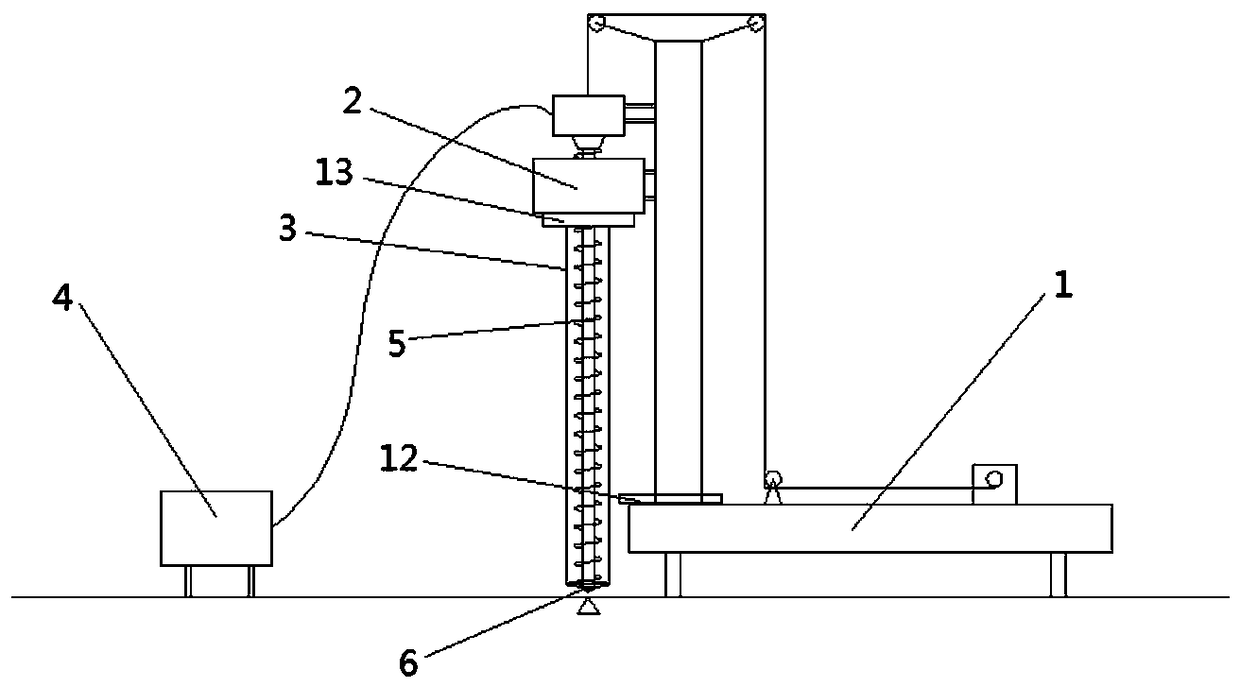
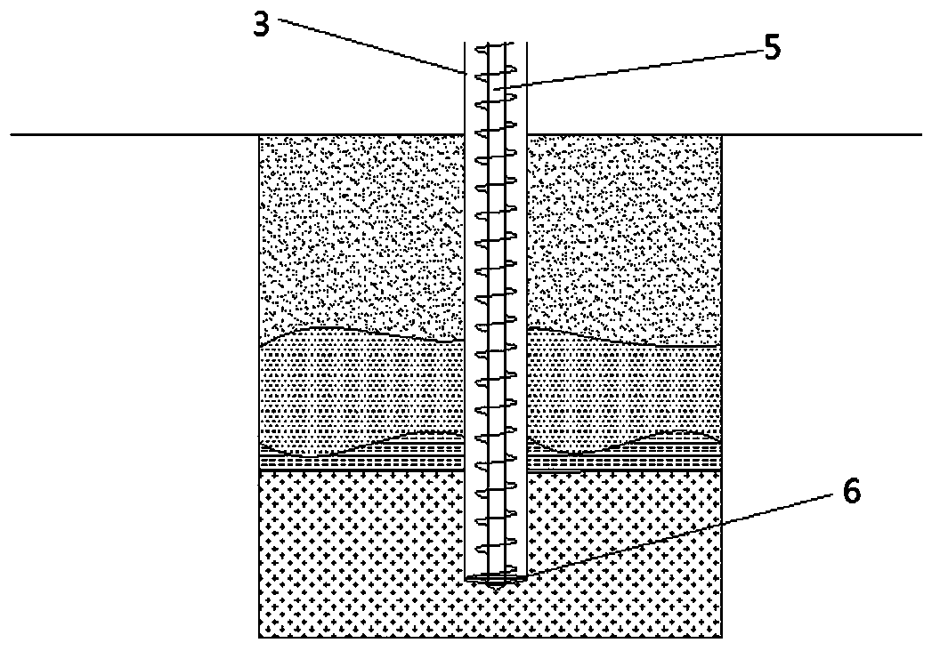
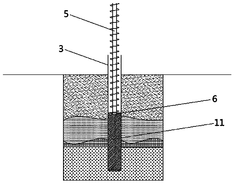
[0031] Example 1, such as figure 1 , figure 2 , image 3 , Figure 4 , Figure 5 , Figure 6 , Figure 7 As shown, the main mechanical equipment and accessories required for the construction of long auger drilled grouting piles with vibrating casing walls in the middle hole include: long auger drilling machine 1, vibrating hammer for middle hole 2, casing 3, tendon inserter 8, small vibration Hammer 7; auxiliary mechanical equipment includes: crane 10, concrete delivery pump 4, excavator. The installation and connection of mechanical equipment includes: the long auger rig 1 connects and drives the auger rod 5 and the drill bit 6; the long auger rig is provided with a cleaner 12, and the middle-hole vibratory hammer 2 clamps the casing 3 with a hydraulic clamp 13. The auger drill pipe 5, drill bit 6, center hole vibratory hammer 2 and casing 3 overlap in the axial direction; the small vibratory hammer 7 is connected to and drives the rib inserter 8; the concrete delivery...


PUM


Abstract

The invention relates to a construction method of a medium-hole vibrating casing wall protection type long spiral cast-in-situ bored pile. The construction method comprises the steps that surveying and setting-out are conducted for determining a pile position, and a long spiral drilling machine is made to be aligned to the pile position; the long spiral drilling machine is started, and a spiral drill rod and a drill bit are driven to conduct rotary drilling vertically downwards; a medium-hole vibrating hammer is started at the same time to drive a pile casing to follow up vertically downwards to a preset pile end depth; the spiral drill rod idles, so that residue soil at the bottom is discharged; the drill rod is lifted, concrete is poured into a pile hole while the spiral drill rod is lifted, and concrete pouring is stopped after the spiral drill rod is lifted to a preset height; after concrete pouring is completed, the pile casing is left in the pile, the long spiral drilling machine is removed out of the pile hole, and a steel bar insertion device and a steel reinforcement cage are inserted into the poured concrete together by means of a crane while being vibrated; and after the steel reinforcement cage is inserted to a preset depth, the steel rib insertion device is pulled out, the pile casing is completely pulled out, and the cast-in-situ pile is solidified and formed. The construction method of the medium-hole vibrating casing wall protection type long spiral cast-in-situ bored pile has the advantages that the quality of the cast-in-site pile is high, construction is safe, the cost is low, the speed is high, environmental friendliness is achieved, and results are practical.

Description

technical field [0001] The invention relates to the technical field of building foundation engineering, in particular to a construction method of a long helical bored grouting pile with a middle-hole vibrating casing retaining wall. Background technique [0002] Cast-in-situ piles have the advantages of no vibration, no soil extrusion, low noise, and are suitable for use in densely built urban areas during construction, and are widely used in construction projects. According to different hole-forming techniques, cast-in-situ piles can be divided into bored cast-in-place piles, sinking tube cast-in-place piles, and artificially dug hole-filled cast-in-place piles. [0003] Bored cast-in-place piles refer to piles that are fully replaced by drilling pile holes with drilling machines and pouring concrete in the holes (or hanging steel cages in the holes first). According to whether the drilling machine adopts the mud retaining process for construction during the drilling proce...

Claims


Application Information

Patent Timeline
Patent Type & Authority Patents(China)
IPC IPC(8): E02D5/38E02D15/04
CPCE02D5/385E02D15/04
Inventor 白培中白鹏辉张彦峰刘明利石磊
Owner HENAN JINYUAN FOUND ENG CO LTD
Learn More