
Self-locking patch board

A plug-in board and self-locking technology, applied to electrical components, coupling devices, circuits, etc., can solve the problems of falling off, inconvenient use, and difficulty in replacing the plug-in board, and achieve the effects of easy promotion, simple operation and low cost.

Inactive Publication Date: 2013-01-23
MIANYANG POWER SUPPLY COMPANY STATE GRID SICHUANELECTRIC POWER +1
View PDF6 Cites 2 Cited by
  • Summary
  • Abstract
  • Description
  • Claims
  • Application Information

AI Technical Summary

Problems solved by technology

[0002] The traditional plug is connected to the power strip, and the pressure is increased by the built-in spring of the power strip. Although this method can play a simple fixing role, it is easy to cause the plug and the Poor contact of the plug board
Especially when the user wants to drive the unfixed plug-in board to move by pulling the plug, the gravity of the plug-in board can be overcome only by small longitudinal friction, so it is easy to cause poor contact or even the plug and the plug-in board to fall off, which is very difficult to use. Inconvenient, seriously affecting people's production and life
For the convenience of moving, a small number of users use electrical tape to fix the plug and the power strip, but this method makes it difficult to replace the power strip

Method used


Image

  • Self-locking patch board
  • Self-locking patch board
  • Self-locking patch board

Examples


Embodiment Construction

[0012] The following will be described in conjunction with the accompanying drawings and specific embodiments.

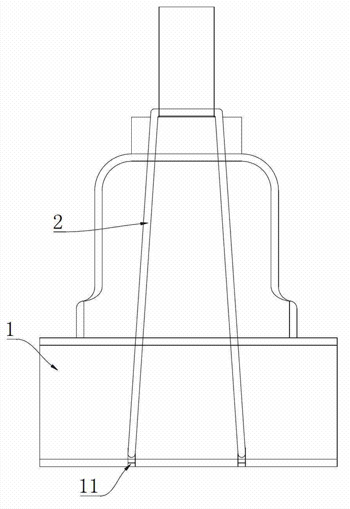
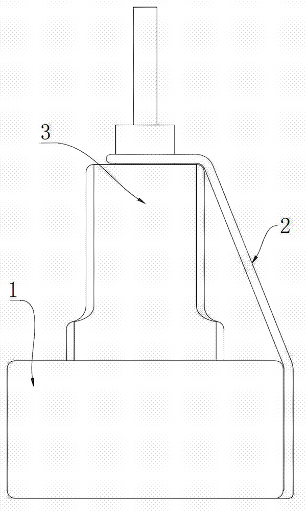
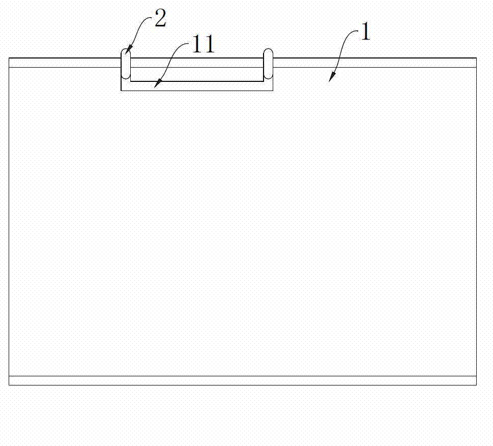
[0013] see Figure 1 to Figure 3 . The self-locking power strip described in this embodiment includes a socket head, a power cord and a power strip body 1 . The bottom side of the plug-in body 1 is provided with a suspension groove 11, and the suspension groove 11 has the same symmetrical plane as the nearest wire insertion hole group. The elastic coil 2 is suspended on the suspension groove 11 . Elastic coil 2 selects rubber band for use in the present embodiment. During use, first take off the rubber ring, after the electric plug 3 is entangled with the rubber ring, the rubber ring is hung on the suspension groove 11 again. The suspended rubber ring tightly pulls the socket body 1 and the electric plug 3, so that the socket body 1 and the electric plug 3 are not easy to fall off under the action of external force.

[0014] The above are only preferred impleme...


PUM


Abstract

The invention discloses a self-locking patch board. The self-locking patch board comprises a socket head, a power cord and a plug row body, wherein a hanging groove is formed on the plug row body, and an elastic coil is hung on the hanging groove. The self-locking patch board can effectively prevent a plug wire head from falling off, and is easy to operate, low in cost, convenient to use and easy to popularize.

Description

technical field [0001] The invention relates to a connector mated with an electric plug. Background technique [0002] The traditional plug is connected to the power strip, and the pressure is increased by the built-in spring of the power strip. Although this method can play a simple fixing role, it is easy to cause the plug and the Poor contact on the power strip. Especially when the user wants to drive the unfixed plug-in board to move by pulling the plug, the gravity of the plug-in board can be overcome only by small longitudinal friction, so it is easy to cause poor contact or even the plug and the plug-in board to fall off, which is very difficult to use. It is inconvenient and seriously affects people's production and life. For the convenience of movement, a small number of users use electrical tape to fix the plug and the power strip, but this method makes it difficult to replace the power strip. Contents of the invention [0003] In view of this, the purpose of ...

Claims


Application Information

Patent Timeline
Patent Type & Authority Applications(China)
IPC IPC(8): H01R13/639
Inventor 贾翔余兰
Owner MIANYANG POWER SUPPLY COMPANY STATE GRID SICHUANELECTRIC POWER
Learn More