Supercharge Your Innovation With Domain-Expert AI Agents!

Branched duct construct, and uniaxial eccentric screw pump system

A structure and screw pump technology, applied to parts of pumping devices for elastic fluids, rotary piston pumps, pumps, etc., can solve the problems of flow path design restrictions, branch flow path difficulties, discharge pressure, and discharge volume Equalization is difficult and other problems, to achieve the effect of simplifying the structure of the flow path and reducing the maintenance time

Active Publication Date: 2013-01-23
HEISHIN ENGINEERING & EQUIPMENT CO LTD
View PDF6 Cites 0 Cited by
  • Summary
  • Abstract
  • Description
  • Claims
  • Application Information

AI Technical Summary

Problems solved by technology

[0004] However, there is a problem that when branching the flow path connected to the uniaxial eccentric screw pump as described above, the number of branches is limited to the n power of 2 ( n=natural number), so that it cannot be divided into the desired number of divergences
In addition, there is also a problem that it is more difficult to equalize the discharge pressure and discharge volume of the fluid discharged from each branch flow path in order to make the arrangement of each branch flow path arbitrarily arranged.
Specifically, there is a problem that complex adjustments such as discharge pressure and discharge volume need to be adjusted by attaching valves, nozzles, etc. to each branch flow path and fine-tuning them.
Therefore, in the prior art, there is a problem that it is extremely difficult to form a branched flow path so that the fluid is discharged to a desired position with a desired number of branches, and the design of the flow path is greatly restricted.
[0005] In addition, when taking measures to adjust the discharge pressure and discharge volume by installing valves, nozzles, etc. on each branch flow path to finely adjust them, there is the following problem: the fine adjustment of the valves and nozzles Need to be skilled, making it difficult to equalize the discharge pressure and discharge volume

Method used


Image

  • Branched duct construct, and uniaxial eccentric screw pump system
  • Branched duct construct, and uniaxial eccentric screw pump system
  • Branched duct construct, and uniaxial eccentric screw pump system

Examples


Embodiment Construction

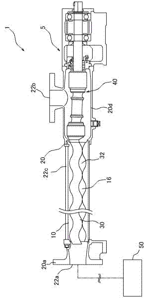
[0035] Next, the uniaxial eccentric screw pump system 1 (hereinafter, simply referred to as "pump system 1") and the branch flow path structure 50 of the present invention will be described in detail with reference to the drawings. The pump system 1 is composed of a single-axis eccentric screw pump 5 and a branch flow path structure 50 . The pump system 1 of the present embodiment is characterized by the branch flow path structure 50 , and before describing this, the structure of the uniaxial eccentric screw pump 5 will be briefly described.

[0036] (About one-axis eccentric screw pump5)

[0037] The one-axis eccentric screw pump 5 is a so-called drum pump, and is configured such that a stator 10 , a rotor 30 , a power transmission mechanism 40 , and the like are housed inside a casing 20 . Such as figure 2 As shown, the stator 10 is a component assembled into the one-axis eccentric screw pump 5, and has an elliptical cross-sectional shape, and is a cylindrical body ha...


PUM


Abstract

Disclosed is a branched duct construct that branches a fluid into a desired number of branches, can dispose the discharge section of each branched duct at a desired position, and can equalize the discharge pressure and discharge quantity at each branched duct. Further disclosed is a uniaxial eccentric screw pump system provided with said branched duct construct. The branched duct (Bn) of the branched duct construct has n relay sections (Rn) so as to correspond to each of n discharge sections (Fn), and has: n systems of introduction-to-relay section ducts (SRn) that connect an introduction section (S) to the relay sections (Rn); and n systems of relay-to-discharge section ducts (RFn) that connect the aforementioned n relay sections (Rn) and discharge sections (Fn). Also, with the branched duct construct, the relay sections (Rn) are disposed at positions corresponding to n points that divide the circumference of an imaginary circle centered around a point on a vertical line passing through the center axis of the introduction section (S), and the branched duct (Bn) is formed in a manner so that the lengths of the n systems of relay-to-discharge section ducts (RFn) are each the same.

Description

technical field [0001] The present invention relates to a branched flow path structure capable of branching fluid introduced into an introduction part into a plurality of systems, and a uniaxial eccentric screw pump system having the branched flow path structure. Background technique [0002] So far, when the non-transported material (fluid) pumped by the uniaxial eccentric screw pump disclosed in the following patent document 1 is divided into a plurality of flow paths, the method of connecting the uniaxial eccentric screw pump to the Countermeasures such as branching of the flow paths one by one. Furthermore, until now, measures have been taken to stabilize the discharge pressure and discharge volume in each branch flow path by providing adjustment valves, nozzles, etc. in each branch flow path and finely adjusting each branch flow path. [0003] Patent Document 1: Japanese Unexamined Patent Publication No. 2008-0175199. [0004] However, there is a problem that when b...

Claims


Application Information

Patent Timeline
IPC IPC(8): F04C2/107F04B53/16F04C14/00
CPCF04C2/1071F04C14/10F04C2240/806
Inventor 榊原教晃高桥洋平
Owner HEISHIN ENGINEERING & EQUIPMENT CO LTD
Features
  • R&D
  • Intellectual Property
  • Life Sciences
  • Materials
  • Tech Scout
  • Unparalleled Data Quality
  • Higher Quality Content
  • 60% Fewer Hallucinations
Learn More