Reverse blowing bag type dust remover

A technology of back-blowing bag type and dust collector, which is applied in chemical instruments and methods, separation of dispersed particles, filtration of dispersed particles, etc. It can solve the problems of poor sealing of compartments, high operation and maintenance costs, and difficulty in achieving the effect of back-blowing and dust removal, etc. Problems, to achieve the effect of less space, good ventilation effect, convenient and simple operation

Inactive Publication Date: 2013-01-30
枣庄市邦众环保设备有限公司
View PDF6 Cites 4 Cited by
  • Summary
  • Abstract
  • Description
  • Claims
  • Application Information

AI Technical Summary

Problems solved by technology

[0002] At present, in the market, there are mostly two types of chamber negative pressure blowback bag filter, one is the low-efficiency rotary dust cleaning back blow bag filter, and the other is the effective room back blow bag filter, but these two Each model has its own shortcomings. The former bag filter adopts the form of rotary back-blowing in the air duct. This kind of dust collector with rotary chamber cleaning has poor sealing performance of the chambers, and it is difficult to achieve efficient back-blowing. Cleaning effect
The other is the reverse blowing bag dust collector with effective compartments. This kind of dust collector uses the ventilation valve and the air distribution channel valve to cooperate with each other, so that the dust collector can switch between the indoor ventilation state and the non-ventilation state for dust removal. process, but the operation and maintenance costs are relatively high

Method used


Image

  • Reverse blowing bag type dust remover
  • Reverse blowing bag type dust remover
  • Reverse blowing bag type dust remover

Examples


Embodiment Construction

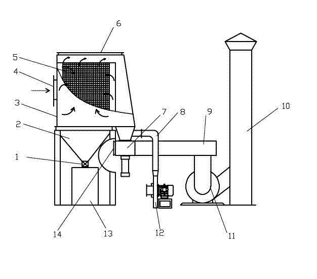
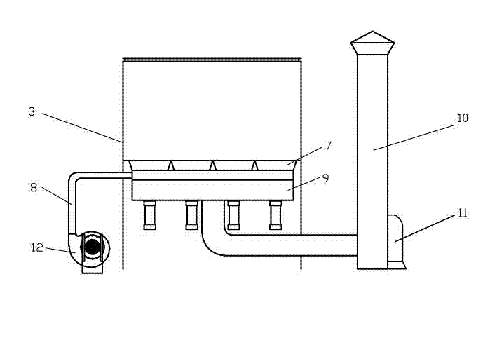
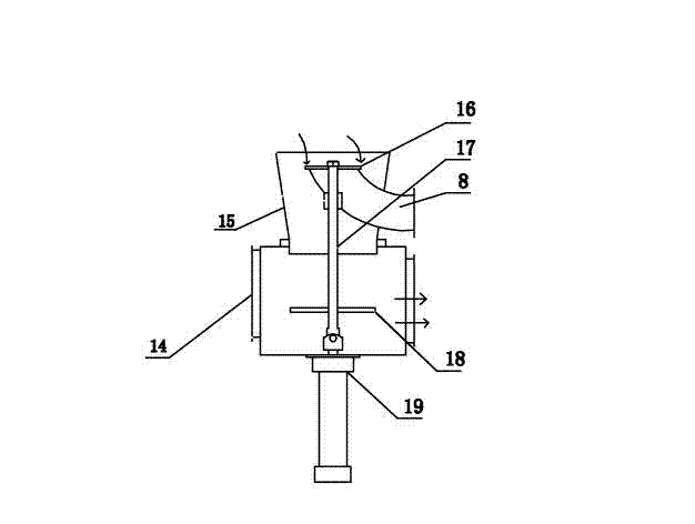
[0021] Such as figure 1 , figure 2 , image 3 As shown, a reverse blowing bag type dust collector comprises an upper box body 3 and a lower box body 2, the lower box body 2 is located below the upper box body 3, and the bottom of the lower box body 2 passes through the ash discharge valve 1 and the ash collection box 13 connection; the inside of the upper box body 3 is provided with a dust removal room, which communicates with the outside through the air inlet on the upper box body 3, and the dust removal room is provided with a dust removal bag, and the dust removal bag is opened on the side wall of the dust removal room; the upper part of the upper box body There is an inspection port, which is closed by a cover door. There is a clean air chamber 6 between the dust removal chamber and the upper box. The lower part of the clean air chamber 6 communicates with the air duct. The chambers are all connected to the air inlet, and correspond to multiple dust removal chambers one...


PUM


Abstract

The invention provides a reverse blowing bag type dust remover comprising an upper box body and a lower box body. A dust removing chamber is arranged inside the upper box body; the dust removing chamber is communicated with the outside through an air inlet on the upper box body; a dust removing bag is arranged inside the dust removing chamber; the opening of the dust removing bag is arranged on the lateral wall of the dust removing chamber; the dust removing chamber is divided into a plurality of relatively independent sub dust removing chambers; an air purifying chamber is divided into a plurality of relatively independent sub air purifying chambers; a combined air duct valve is connected with the lower part of each air purifying chamber; the composite air duct valve is a three-way valve and is connected with two air ducts of a reverse blowing air duct and a mixed air outlet channel; a sealing board is designed inside the combined air duct valve; and the sealing board does reciprocating motion to respectively seal and block the reverse blowing air duct and the mixed air outlet channel. The reverse blowing bag type dust remover provided by the invention is wide in application range and is suitable for removing dust in various heavy-dust fields. The reverse blowing bag type dust remover uses the sub chambers to efficiently reversely remove dust without stopping and removing the dust, and can be used for entirely removing the dust.

Description

technical field [0001] The invention relates to a purification and dust removal equipment, in particular to a dust removal device widely used in production workshops producing heavy dust. Background technique [0002] At present, in the market, there are mostly two types of chamber negative pressure blowback bag filter, one is the low-efficiency rotary dust cleaning back blow bag filter, and the other is the effective room back blow bag filter, but these two Each model has its own shortcomings. The former bag filter adopts the form of rotary back-blowing in the air duct. This kind of dust collector with rotary chamber cleaning has poor sealing performance of the chambers, and it is difficult to achieve efficient back-blowing. Cleaning effect. The other is the reverse blowing bag dust collector with effective compartments. This kind of dust collector uses the ventilation valve and the air distribution channel valve to cooperate with each other, so that the dust collector can...

Claims


Application Information

Patent Timeline
Patent Type & Authority Applications(China)
IPC IPC(8): B01D46/04
Inventor 王钦海
Owner 枣庄市邦众环保设备有限公司
Why Eureka
Try Eureka