
Drive system for driving moving walkways

A technology of moving walks and drive systems, applied in the direction of energy efficiency of escalators, escalators, sustainable buildings, etc., can solve problems such as excessive application

Inactive Publication Date: 2013-01-30
THYSSENKRUPP ELEVATOR INNOVATION CENT SA
View PDF10 Cites 4 Cited by
  • Summary
  • Abstract
  • Description
  • Claims
  • Application Information

AI Technical Summary

Problems solved by technology

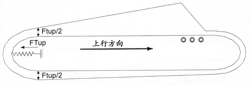
[0011] Another disadvantage of having the drive unit at only one end is that, for very long horizontal walkways, it is necessary in the case of the "down" direction (drive unit in the upper head) from the The tensioning station in the opposite head exerts excessive force in order to prevent areas with excessive negative stress in the chain / belt of the pedal

Method used


Image

  • Drive system for driving moving walkways
  • Drive system for driving moving walkways
  • Drive system for driving moving walkways

Examples


Embodiment Construction

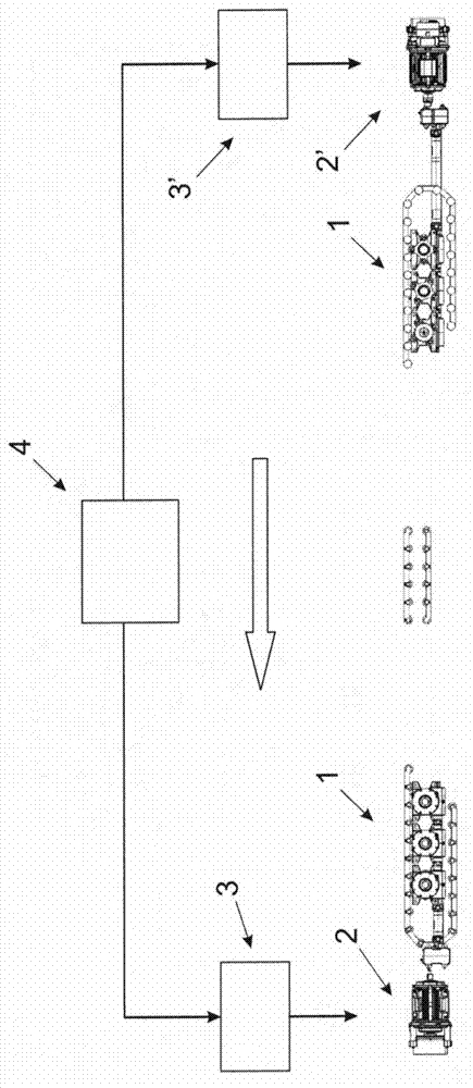
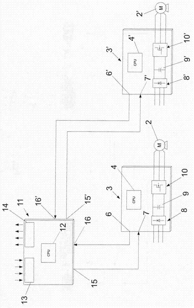
[0035] figure 1 The different components of the drive system of the invention are schematically shown, comprising the drive system 1 of the belt of the pedals and the drive unit at each end of the walkway, said drive unit being driven by one or more motors 2 - 2', a control device 3-3' for controlling the motor 2-2' and a general control device 4 for controlling the system are constituted.

[0036] A preferred but not exclusive embodiment of a drive system for a belt driving pedals is described in ES 2342532 from the same applicant, such as Figure 6 Shown in includes a series of wheels 5 with rollers 5'. The wheel 5 is arranged on an axis 6 perpendicular to the direction of movement of the belt 1 of the pedal. The shaft 6 is driven by one or more motors via a series of transmissions, eg gears. Power is transmitted to the belt 1 of the pedal by engaging the roller 5' in the engagement structure 7 of the pedal.

[0037]The control device 3-3' for controlling the motor ...


PUM


Abstract

The present invention relates to a drive system for driving moving walkways, comprising a drive unit (2-2') arranged at each end of the walkway (1), control means (3-3') for controlling each drive unit and overall control means (4) for controlling the set of drive units (2-2').

Description

technical field [0001] The present invention relates to a drive system for driving a moving walkway, and more particularly for driving a moving walkway for transporting people and goods, said moving walkway being formed by an endless belt of treads moving on side guides . [0002] Conventional moving walks used for the above purposes consist of a set of treads moving on guide plates, said treads being fixed and fitted to a structure supporting the members and the weight of the user. The walkways are also provided with glass or opaque railings, also fixed to the same support structure, on which the handrails move at the same speed as the treads. Background technique [0003] Conventional systems for transporting passengers / goods, such as moving walkways, comprise a chain of conveyor treads moving in tracks for the purpose of providing continuous movement along a specific path. Conveyor treads are connected to said chain track which causes movement due to a drive system. Th...

Claims


Application Information

Patent Timeline
Patent Type & Authority Applications(China)
IPC IPC(8): B66B23/02B66B25/00
CPCB66B25/00B66B25/003B66B23/026B66B23/02Y02B50/225Y02B50/00
Inventor M·A·冈萨雷斯·阿莱马尼F·坎泰利·阿尔瓦雷斯A·弗洛雷斯·卡斯特罗A·坎西奥·费维恩扎J·奥赫达·阿雷纳斯A·佩罗·加西亚
Owner THYSSENKRUPP ELEVATOR INNOVATION CENT SA
Learn More