Tap hole replacing device

A technology of tapping hole and driving device, which is applied in the manufacture of converters, etc., can solve problems such as loss of refractory materials, high labor intensity, and potential safety hazards, and achieve the effects of shortening replacement time, reducing labor intensity, and improving installation accuracy

Active Publication Date: 2013-01-30
PANGANG GRP XICHANG STEEL & VANADIUM CO LTD
View PDF8 Cites 8 Cited by
  • Summary
  • Abstract
  • Description
  • Claims
  • Application Information

AI Technical Summary

Problems solved by technology

In the process of replacing the taphole, there are usually many safety hazards (falling from high altitude, slag collapse, burns, etc.), and at the same time, the replacement time is long, the cost is high, the labor intensity is high, and the loss of refractory materials is serious.
[0004] The Chinese patent application with the publication number CN202063944U discloses a platform for replacing the tapping hole of a converter. The height of the taphole reduces the number of operators and improves the replacement quality of the taphole. However, in the process of replacing the taphole, it is still necessary to manually insert the taphole into the taphole hole, which is labor intensive. And it is inconvenient to change the insertion depth of the tapping hole. Moreover, the tapping hole replacement platform does not solve the problems that need to be solved in the filling process of the tapping hole refractory material. For example, the filling accuracy of the refractory material cannot be accurately controlled, and the high temperature furnace of the converter cannot be avoided. The baking injury of the fire to the workers, the protection of the life safety of the workers, etc.

Method used


Image

  • Tap hole replacing device
  • Tap hole replacing device
  • Tap hole replacing device

Examples


Embodiment Construction

[0031] The tap changing device according to the present invention will be described in detail below with reference to the accompanying drawings and exemplary embodiments.

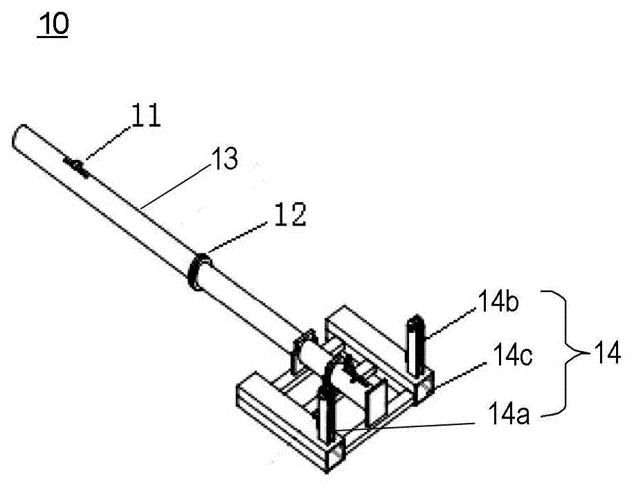
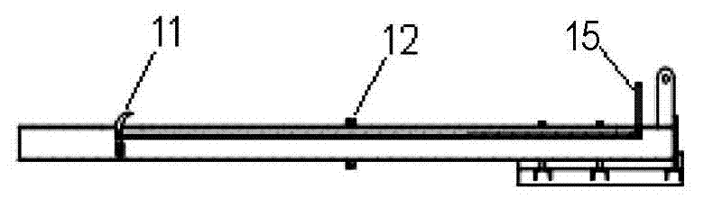
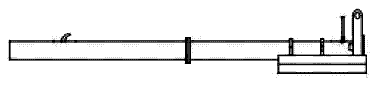
[0032] Figure 1A is a perspective view of the tapping hole replacement device according to an exemplary embodiment of the present invention; Figure 1B is a cross-sectional view of a tapping hole replacement device according to an exemplary embodiment of the present invention; Figure 1C is a side view of a tapping hole replacement device according to an exemplary embodiment of the present invention; Figure 1D is a top view of the tapping hole replacement device of an exemplary embodiment of the present invention; Figure 2A A side view of the safety guard of the tap changer according to an exemplary embodiment of the present invention; Figure 2B A perspective view of the safety guard of the tapping hole replacement device according to the exemplary embodiment of the present invention; Figure 3A is a...


PUM


Abstract

The invention provides a tap hole replacing device. The tap hole replacing device comprises an ejector rod mechanism, and a drive device capable of moving the ejector rod mechanism, wherein the ejector rod mechanism comprises an ejector rod, a blocking part and a limiting part, wherein the exterior of the ejector rod is sleeved with a tap hole; the blocking part and the limiting part are respectively arranged on the outer wall of the ejector rod, the blocking part is at a blocking position or a loosening position along a radial direction of the ejector rod, when the blocking part is at the blocking position, the blocking part and the inner end of a furnace on the tap hole are clamped, when the blocking part is at the loosening position, the inner end of the furnace on the tap hole is loosened by the blocking part, and the limiting part is capable of limiting the motion of the outer end of the furnace on the tap hole so as to prevent the outer end of the furnace from moving to a direction far away from the blocking part. According to the tap hole replacing device, provided by the invention, the insertion depth of the tap hole is changed, the labor intensity is reduced, and the tap hole replacing efficiency is improved.

Description

technical field [0001] The present invention relates to a device for replacing a tap hole, and more particularly, to a device for replacing a converter tap hole. Background technique [0002] The tap hole of the converter is the only channel for molten steel to enter the ladle from the converter. During the tapping process, the tap hole is subjected to frictional erosion and oxidative erosion of high temperature molten steel and slag, resulting in a very low life of the tap hole, and it is necessary to continuously adjust the tapping hole. Steel ports are repaired and replaced. [0003] At present, the common method is to replace the tap hole manually, use a crane or forklift to lift the tap hole to the work place, manually insert the tap hole into the tap hole, adjust it to a suitable position, and then use the " The refractory material is thrown around the tap hole by using a shovel, that is, the staff in front of the furnace use a shovel to drop the mixed refractory mate...

Claims


Application Information

Patent Timeline
Patent Type & Authority Applications(China)
IPC IPC(8): C21C5/46
Inventor 曹之斌卓钧董克平
Owner PANGANG GRP XICHANG STEEL & VANADIUM CO LTD
Why Eureka
Try Eureka