A compressor gas-liquid separation structure

A gas-liquid separation and compressor technology, which is applied in the direction of refrigerators, mechanical equipment, refrigeration and liquefaction, etc., can solve the problems of cost increase, increase in external size, unfavorable internal structure optimization, etc., achieve strong applicability, improve gas-liquid Effect of Separation Accuracy

Active Publication Date: 2015-10-07
GREE ELECTRIC APPLIANCES INC
View PDF7 Cites 0 Cited by
  • Summary
  • Abstract
  • Description
  • Claims
  • Application Information

AI Technical Summary

Problems solved by technology

Due to the limitation of the size and precision of the filter, in order to obtain a better filtering effect, the mesh number of the gas-liquid filter is getting denser. At the same time, in order to ensure a certain pressure loss, the shape of the gas-liquid filter needs to be further enlarged, resulting in cost The increase of the external size increases at the same time, which is not conducive to the optimization of the internal structure

Method used


Image

  • A compressor gas-liquid separation structure
  • A compressor gas-liquid separation structure

Examples


Embodiment Construction

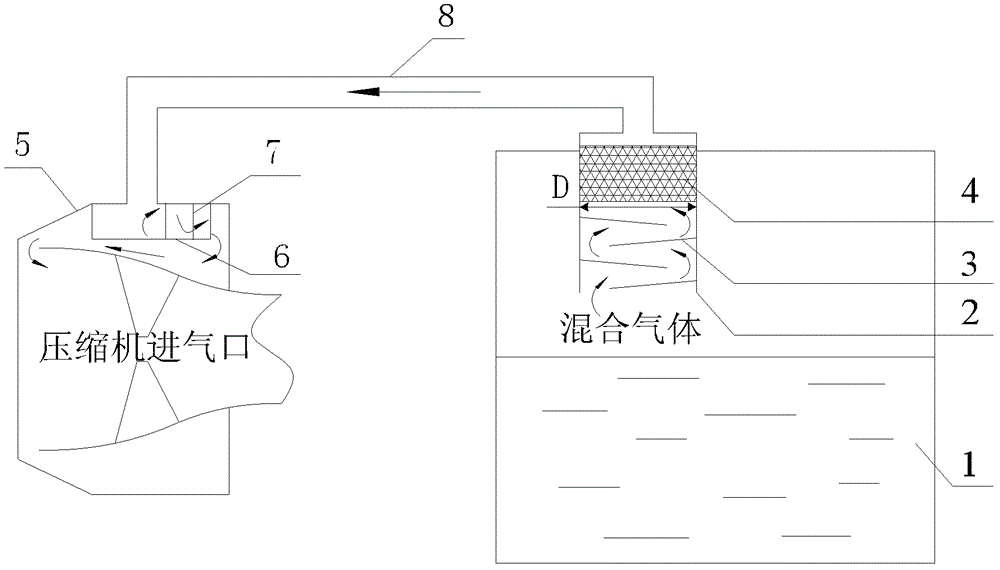
[0019] The embodiment of the present invention provides a compressor gas-liquid separation structure, which is used to achieve gas-liquid separation by utilizing the property that the liquid droplets are easy to attach to barriers due to the existence of viscosity when the flow velocity of the gas-liquid mixture decreases and the flow direction changes. The purpose is to obtain higher separation precision through multiple baffles and improve the separation effect of the gas-liquid mixture formed by refrigerant and lubricating oil in the compressor system.

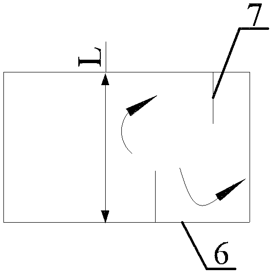
[0020] refer to figure 1 , shows a gas-liquid separation structure of a compressor according to an embodiment of the present invention, which includes a primary baffle set 3, a gas-liquid filter 4, and is further provided with a baffle 6 and a secondary baffle set 7, Among them, the primary baffle group 3 and the gas-liquid filter screen 4 are arranged in the same cylinder 2 on the top of the compressor oil tank 1, and the ...


PUM


Abstract

An embodiment of the invention discloses a gas-liquid separation structure for a compressor. The gas-liquid separation structure for the compressor is used for improving separation effect of gas-liquid mixture formed by refrigerant and lubricant in a compressor system, and comprises a primary baffle group, a gas-liquid filter screen and a secondary baffling component. The secondary baffling component comprises a secondary baffle group and a baffle arranged at a gas suction port of the compressor. The gas-liquid mixture flows through the primary baffle group and the gas-liquid filter screen for primary separation and then flows through the second baffle component for secondary separation.

Description

technical field [0001] The invention relates to the field of air conditioning, in particular to a compressor gas-liquid separation structure. Background technique [0002] For the centrifugal unit, in order to ensure the normal lubrication of the bearing and the evaporation of the relatively pure refrigerant in the evaporator to ensure the high performance of the unit, it is necessary to fully separate the refrigerant and lubricating oil. Especially for the pressure balance pipe in the oil tank, in order to reduce the pressure of the oil tank, the balance pipe is led to the air inlet of the compressor, which will cause the mixture of refrigerant and oil to enter the compressor system, affecting the normal lubrication of the bearing and the purity of the refrigerant. For this problem, the conventional solution is to install a gas-liquid filter at the outlet of the fuel tank to achieve the purpose of gas-liquid separation. Due to the limitation of the size and precision of th...

Claims


Application Information

Patent Timeline
Patent Type & Authority Patents(China)
IPC IPC(8): F25B43/02F04D29/70
Inventor 钟瑞兴张治平蒋楠陈杰东蒋彩云谢蓉
Owner GREE ELECTRIC APPLIANCES INC
Why Eureka
Try Eureka