Supercharge Your Innovation With Domain-Expert AI Agents!

Method for determining amount of ball placement for camera module

A camera module and ball planting technology, which is applied in semiconductor/solid-state device testing/measurement, electrical components, electric solid-state devices, etc., can solve the problems of increasing packaging costs and skewing of chips 12, so as to avoid skewing, alleviate height unevenness, The effect of improving the packaging quality

Inactive Publication Date: 2015-05-20
PRIMAX ELECTRONICS LTD
View PDF2 Cites 0 Cited by
  • Summary
  • Abstract
  • Description
  • Claims
  • Application Information

AI Technical Summary

Problems solved by technology

Although this can prevent the raised edge 113 from forming a fulcrum with the chip 12, the heights of the contacts 111 of the substrate 11 corresponding to the pads 122 are not the same. If only the same number of conductive blocks 13 are placed on each pad 122, Not only does it increase unnecessary packaging costs, it is more likely that the chip 12 will be skewed due to the problem of uneven height of the contacts 111

Method used


Image

  • Method for determining amount of ball placement for camera module
  • Method for determining amount of ball placement for camera module
  • Method for determining amount of ball placement for camera module

Examples


Embodiment Construction

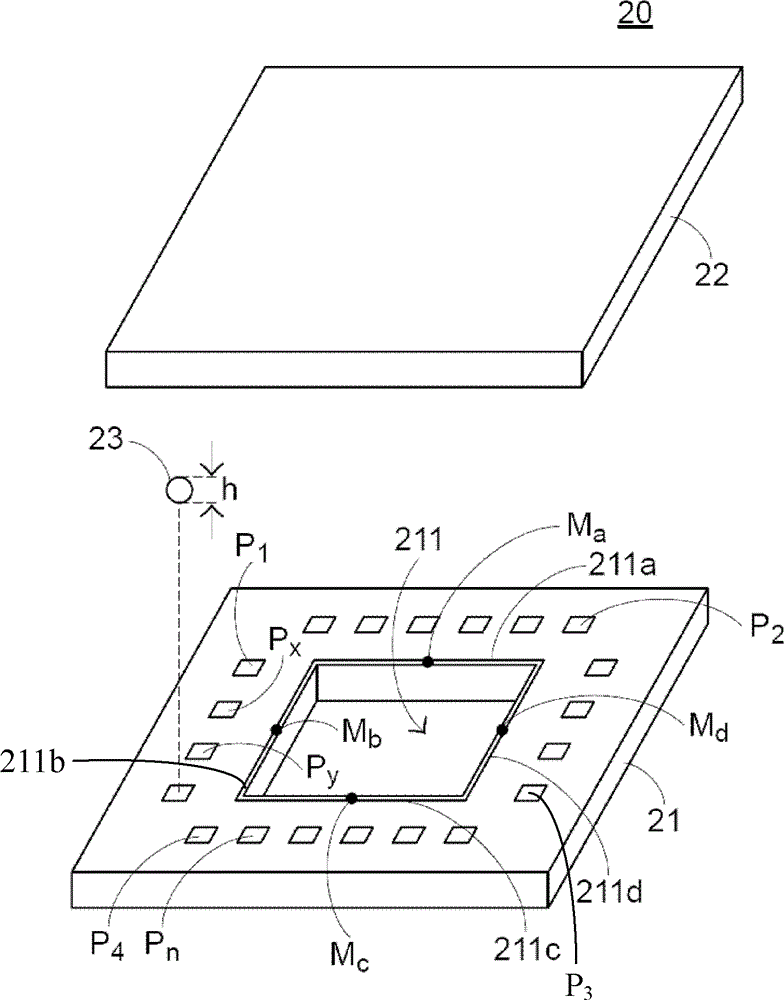
[0025] Please refer to image 3 , image 3 It is a schematic diagram of the camera module of the present invention. Such as image 3 As shown, the camera module 20 includes a substrate 21 and a chip 22 . The substrate 21 has an opening 211 and a plurality of contacts Pn, where n=1˜n and n is a positive integer. The opening 211 has four borders 211a, 211b, 211c, 211d, and each contact Pn is used to receive at least one conductive block, especially a ball plant 23 made of conductive metal, so as to electrically connect and fix the substrate 21 and the chip 22 . In addition, the planted ball 23 has a planted ball height h.

[0026] The method for determining the number of planted balls of the camera module in the present invention is as follows, please refer to Figure 4 , Figure 4 It is a schematic diagram of the machine platform of the present invention. Such as Figure 4 As shown, the machine 30 has a platform 31 and an image capture device 32, wherein the platform 31...


PUM


Abstract

The invention discloses a method for determining amount of ball placement for a camera module. The camera module comprises a substrate and a chip. The substrate is provided with an opening and a plurality of contacts. The opening of the substrate is provided with a square frame. An image acquisition device is used to acquire distances from at least four specific contacts on the substrate to the image acquisition device, a distance from the square frame of the opening to an opening of the image acquisition device, a distance from each contact on the substrate to an actual contact of the image acquisition device so as to obtain an average contact distance, a smallest opening distance and a plurality of actual contact distances. The amount of ball placement for each contact is calculated according to the distances, so that packaging quality of the camera module is improved.

Description

technical field [0001] The invention relates to a method for determining the quantity of balls to be planted, in particular to a method for determining the quantity of balls to be planted in a camera module. Background technique [0002] At present, most of the camera modules 10 are assembled by flip-chip (Flip-Chip) packaging technology, such as figure 1 as shown, figure 1 It is a schematic diagram of an existing camera module. The camera module 10 includes a substrate 11 and a chip 12, wherein the substrate 11 has a contact point 111 and an opening 112, the chip 12 has a sensing area 121 and pads 122, and each pad 122 is provided with a conductive block 13 for The contacts 111 and the pads 122 are electrically connected to fix the substrate 11 and the chip 12 . [0003] read on figure 1 , the contacts 111 are distributed around the opening 112, corresponding to the pads 122, and the opening 112 of the substrate 11 is formed by punching a hole element. However, when th...

Claims


Application Information

Patent Timeline
Patent Type & Authority Patents(China)
IPC IPC(8): H01L21/60H01L21/603H01L21/66
CPCH01L24/81
Inventor 吕思豪余建男
Owner PRIMAX ELECTRONICS LTD
Features
  • R&D
  • Intellectual Property
  • Life Sciences
  • Materials
  • Tech Scout
  • Unparalleled Data Quality
  • Higher Quality Content
  • 60% Fewer Hallucinations
Learn More